Skip to content

Knowledge Base#

Welcome to the VergeOS Knowledge Base

Overview

Key Points

  • The VergeOS Knowledge Base contains troubleshooting guides, best practices, and how-to articles
  • Use the search function, categories, and tags to find relevant information quickly
  • Articles follow a consistent format with overview, prerequisites, steps, and troubleshooting sections
  • Updated regularly to reflect the latest VergeOS features and improvements

Welcome to the VergeOS Knowledge Base! This resource is designed to help you find solutions quickly, optimize your VergeOS environment, and troubleshoot common issues. Whether you're new to VergeOS or an experienced administrator, this guide will help you navigate our documentation effectively.

How to Use the Knowledge Base

Search Functionality

The fastest way to find specific information is through our search function:

  1. Use the search bar at the top of the page
  2. Enter keywords related to your question or issue
  3. Review the search results to find relevant articles
  4. For more focused results, use specific terms (e.g., "UEFI VM boot" instead of just "boot")

Articles are organized into logical categories to help you browse related content:

  • Getting Started: Introductory guides and basic concepts
  • Installation: Guides for installing and setting up VergeOS
  • Virtual Machines: Everything related to virtual machines
  • Networking: Network configuration and troubleshooting
  • Storage & vSAN: Storage management and optimization
  • Tenants: Multi-tenancy setup and management
  • Troubleshooting: Common issues and their solutions
  • API & Automation: Programmatic access and automation guides
  • Best Practices: Recommendations for optimal performance

Using Tags

Tags provide another way to discover related content:

  1. Articles are tagged with relevant keywords
  2. Click on a tag to see all articles with that tag
  3. Use tags to find specific technologies or features (e.g., "UEFI", "virtio", "snapshot")

Understanding Article Structure

Each article follows a consistent format to help you quickly find the information you need:

  1. Title & Overview: A brief description of what the article covers
  2. Key Points: Important takeaways highlighted at the beginning
  3. Prerequisites: What you need before starting
  4. Steps: Clear, numbered instructions
  5. Troubleshooting: Common issues and solutions
  6. Additional Resources: Related articles and external references
  7. Document Information: Last update date and applicable VergeOS version

Types of Content

How-To Guides

Step-by-step instructions for completing specific tasks, such as:

  • Creating a new VM
  • Setting up network routing
  • Configuring backups

Troubleshooting Articles

Guides to diagnose and resolve common issues:

  • VMs not booting
  • Network connectivity problems
  • Storage performance issues

Best Practices

Recommendations for optimizing your VergeOS environment:

  • VM sizing guidelines
  • Network design principles
  • Storage tier usage

Reference Information

Detailed technical information:

  • API documentation
  • Configuration parameters
  • System requirements

Contributing to the Knowledge Base

We continuously improve our documentation based on user feedback:

  • At the bottom of each article, you'll find a "Need Help?" section where you can provide feedback
  • If you discover outdated information or errors, please let us know
  • Suggest new topics that should be covered in the Knowledge Base

Staying Updated

The Knowledge Base is regularly updated to reflect the latest VergeOS features, improvements, and fixes:

  • Check the "Last Updated" date at the bottom of each article
  • Articles are tagged with the applicable VergeOS version
  • New content is added regularly based on user feedback and product updates

Additional Support Resources

If you can't find what you're looking for in the Knowledge Base:

  • Product Guide: For comprehensive information about VergeOS features and capabilities
  • Support Portal: Submit support tickets and track their progress
  • Community Forums: Connect with other VergeOS users and share experiences

Feedback

Need Help?

If you have suggestions for improving the Knowledge Base or can't find the information you're looking for, please reach out to our support team. We're committed to making our documentation as helpful and comprehensive as possible.


Document Information

  • Last Updated: 2025-03-10
  • VergeOS Version: 4.13.0

VM Lifecycle Management API Overview

Key Points

  • Complete REST API for virtual machine lifecycle management and automation
  • Programmatically create, configure, manage, and delete VMs using HTTP endpoints
  • Four-stage API workflow: Creation → Power Management → Configuration → Advanced Operations
  • Comprehensive API documentation optimized for developers and automation tools

Stage: API Overview (Entry Point) Input: Developer requirements, automation needs Output: Guided workflow to specific API documentation Navigation Path: - Start here → Choose specific operation → Follow detailed guides - Complete lifecycle: Creation → Power → Configuration → Advanced

This Document Helps With

  • "VM API overview and getting started"
  • "REST API workflow for VM management"
  • "API endpoint reference and navigation"
  • "Developer onboarding for VergeOS APIs"
  • "Infrastructure as code planning"
  • "Automation workflow design"
  • "API integration guidance"
  • "VM management automation strategy"

API Workflow Stages

1. VM Creation API

Create virtual machines programmatically with drives, devices, and network interfaces using REST API calls. → See: VM-Creation-API.md

2. VM Power Management API

Start, stop, reboot, and monitor VM power states through API endpoints. → See: VM-Power-Management.md

3. VM Configuration API

Modify CPU, RAM, storage drives, and network settings via API calls. → See: VM-Configuration.md

4. Advanced VM Operations API

Clone VMs, create snapshots, delete virtual machines, and troubleshoot issues using API methods. → See: VM-Advanced-Operations.md

Key API Concepts

  • VM Key vs Machine Key: API distinction for VM settings vs hardware operations
  • REST API Authentication: Bearer token authentication required for all API calls
  • Resource Groups: UUID-based API parameters for device passthrough (GPUs, PCI devices)
  • Storage Tiers: API-configurable performance levels (1-5) for drive placement
  • HTTP Methods: GET, POST, PUT, DELETE operations for complete VM lifecycle management

Primary API Endpoints

API Operation HTTP Method REST Endpoint Purpose
Create VM POST /api/v4/vms Create new virtual machine
VM Actions POST /api/v4/vm_actions Power operations, clone, snapshot
Update VM PUT /api/v4/vms/{id} Modify VM configuration
Add Storage POST /api/v4/machine_drives Attach drives to VM
Add Network POST /api/v4/machine_nics Configure network interfaces
Add Devices POST /api/v4/machine_devices Attach GPU/PCI devices
Delete VM DELETE /api/v4/vms/{id} Remove virtual machine
VM Status GET /api/v4/vms/{id} Query VM information
Power State GET /api/v4/machine_status/{id} Check runtime status

API Quick Reference by Stage

Stage Primary Operations Key Endpoints Documentation
Creation Create VM, Add drives, Add NICs, Add devices POST /api/v4/vms, POST /api/v4/machine_* VM-Creation-API.md
Power Start, Stop, Reboot, Monitor POST /api/v4/vm_actions, GET /api/v4/machine_status VM-Power-Management.md
Config Update CPU/RAM, Manage drives, Manage NICs PUT /api/v4/vms, POST/PUT/DELETE /api/v4/machine_* VM-Configuration.md
Advanced Clone, Snapshot, Delete, Troubleshoot POST /api/v4/vm_actions, DELETE /api/v4/vms VM-Advanced-Operations.md

Common API Error Scenarios

  • Authentication Issues: Invalid API key, expired tokens, insufficient permissions
  • Resource Constraints: Insufficient storage, memory limits, CPU quotas exceeded
  • Configuration Errors: Invalid parameters, missing required fields, malformed JSON
  • State Conflicts: VM already running, operation in progress, resource locked
  • Network Issues: API timeout, connection refused, service unavailable
  • Validation Errors: Invalid VM names, unsupported configurations, constraint violations

API Getting Started Guide

  1. Create VMs: VM-Creation-API.md - REST API calls to create virtual machines
  2. Power Control: VM-Power-Management.md - API endpoints to start, stop, and manage VMs
  3. Configure VMs: VM-Configuration.md - API methods to modify VM settings and hardware
  4. Advanced Operations: VM-Advanced-Operations.md - API calls for cloning, backup, and troubleshooting

Common API Use Cases

  • Automated VM Provisioning: Create VMs programmatically for cloud automation
  • Infrastructure as Code: Manage virtual machine infrastructure through API calls
  • DevOps Integration: Integrate VM management into CI/CD pipelines using REST APIs
  • Monitoring and Alerting: Query VM status and power states via API endpoints
  • Backup and Recovery: Automate VM snapshots and cloning through API operations
  • Resource Management: Programmatically manage VM CPU, memory, and storage allocation

API Authentication

All VM lifecycle API endpoints require authentication:

curl -H "Authorization: Bearer YOUR_API_KEY" \
     -H "Content-Type: application/json" \
     https://your-vergeos.example.com/api/v4/vms

Start with the VM Creation API documentation to begin automating your virtual machine management workflows.

VM Advanced Operations API

Key Points

  • Clone VMs with complete configuration and drive copying
  • Create and restore VM snapshots for backup and recovery
  • Safely delete VMs with automatic resource cleanup
  • Comprehensive error handling and troubleshooting guidance

This guide covers advanced virtual machine operations in VergeOS, including cloning, snapshot management, deletion, and troubleshooting. These operations provide powerful capabilities for VM lifecycle management and disaster recovery.

Stage: VM Advanced Operations (4 of 4) Input: VM key (42), operation type, parameters Output: Cloned VMs, snapshots, cleanup confirmation Previous: VM configured → VM-Configuration.md Common Operations: - Clone for templates → New VM creation cycle - Snapshot for backup → Recovery workflows - Delete for cleanup → End of lifecycle

This Document Helps With

  • "How to clone VMs via API"
  • "Creating VM snapshots and backups"
  • "Restoring VMs from snapshots"
  • "Safely deleting VMs and cleanup"
  • "VM troubleshooting and diagnostics"
  • "Template creation workflows"
  • "Disaster recovery operations"
  • "Bulk VM management"
  • "Resource cleanup automation"

Quick Reference

Primary Endpoints

  • VM Actions: POST /api/v4/vm_actions
  • VM Deletion: DELETE /api/v4/vms/{vm_key}
  • VM Listing: GET /api/v4/vms

Key Actions

  • clone: Create complete VM copy
  • snapshot: Create VM snapshot
  • restore: Restore from snapshot

Authentication

-H "Authorization: Bearer YOUR_API_KEY"
-H "Content-Type: application/json"

Prerequisites

VM must exist → See VM-Creation-API.md

API Quick Reference

Operation Method Endpoint Key Type Purpose
Clone VM POST /api/v4/vm_actions VM key Create complete copy
Create Snapshot POST /api/v4/vm_actions VM key Point-in-time backup
Restore Snapshot POST /api/v4/vm_actions VM key Recovery operation
List Snapshots GET /api/v4/vms Filter query Find snapshots
Delete VM DELETE /api/v4/vms/{id} VM key Complete removal
VM Status GET /api/v4/vms/{id} VM key Configuration check
Operation Status GET /api/v4/machine_status/{id} Machine key Runtime monitoring

Troubleshooting Index

  • 409 Conflict: Clone name exists, VM already running, operation in progress
  • 507 Insufficient Storage: Not enough space for clone, snapshot storage full
  • 403 Forbidden: API key permissions, VM access denied, cluster restrictions
  • 404 Not Found: VM not found, snapshot not found, invalid VM key
  • 408 Request Timeout: Clone operation timeout, snapshot creation timeout
  • 422 Unprocessable Entity: Invalid clone parameters, snapshot restore conflict
  • 500 Internal Server Error: Storage system issues, hypervisor problems, cluster failures

VM Cloning

POST /api/v4/vm_actions

Description: Creates a complete copy of a VM including all drives and configuration.

Basic Clone

{
  "params": {
    "name": "test clone",
    "quiesce": "true"
  },
  "action": "clone",
  "vm": "42"
}

Complete API Call:

curl -X POST "https://your-vergeos.example.com/api/v4/vm_actions" \
  -H "Authorization: Bearer YOUR_API_KEY" \
  -H "Content-Type: application/json" \
  -d '{
    "params": {
      "name": "test clone",
      "quiesce": "true"
    },
    "action": "clone",
    "vm": "42"
  }'

Response Example:

{
  "response": {
    "vmkey": "43",
    "machinekey": "55",
    "machinestatuskey": "55",
    "clusterkey": "1"
  }
}

Advanced Clone Options

{
  "params": {
    "name": "production-clone",
    "description": "Production server clone for testing",
    "preserve_macs": "true",
    "preserve_device_uuids": "true",
    "quiesce": "true",
    "cluster": "2"
  },
  "action": "clone",
  "vm": "42"
}

Clone Parameters

Parameter Type Required Description
name string Yes Name for the cloned VM
description string No Description for the clone
quiesce string No Quiesce VM before cloning ("true"/"false") for data consistency
preserve_macs string No Preserve MAC addresses ("true"/"false")
preserve_device_uuids string No Preserve device UUIDs ("true"/"false")
cluster string No Target cluster ID

Clone Options

  • Quiesce: Use "quiesce": "true" to ensure data consistency by pausing the VM briefly
  • Preserve MACs: Use "preserve_macs": "true" to keep the same MAC addresses (may cause network conflicts)
  • Preserve Device UUIDs: Use "preserve_device_uuids": "true" to maintain device identifiers
  • Cross-Cluster: Specify different cluster ID to clone to another cluster

Clone Workflow Example

# Step 1: Create clone
curl -X POST "https://your-vergeos.example.com/api/v4/vm_actions" \
  -H "Authorization: Bearer YOUR_API_KEY" \
  -H "Content-Type: application/json" \
  -d '{
    "params": {
      "name": "backup-clone-$(date +%Y%m%d)",
      "description": "Automated backup clone",
      "quiesce": "true"
    },
    "action": "clone",
    "vm": "42"
  }'

# Step 2: Verify clone creation (using returned vmkey)
curl "https://your-vergeos.example.com/api/v4/vms/43?fields=name,description,created" \
  -H "Authorization: Bearer YOUR_API_KEY"

# Step 3: Check clone power state
curl "https://your-vergeos.example.com/api/v4/machine_status/55?fields=powerstate,status" \
  -H "Authorization: Bearer YOUR_API_KEY"

VM Snapshots

Creating Snapshots

{
  "vm": "42",
  "action": "snapshot",
  "params": {
    "name": "pre-update-snapshot",
    "description": "Before system update"
  }
}

Complete API Call:

curl -X POST "https://your-vergeos.example.com/api/v4/vm_actions" \
  -H "Authorization: Bearer YOUR_API_KEY" \
  -H "Content-Type: application/json" \
  -d '{
    "vm": "42",
    "action": "snapshot",
    "params": {
      "name": "pre-update-snapshot",
      "description": "Before system update - $(date)"
    }
  }'

Restoring from Snapshots

{
  "vm": "42",
  "action": "restore",
  "params": {
    "snapshot_id": "snapshot-67890"
  }
}

Complete API Call:

curl -X POST "https://your-vergeos.example.com/api/v4/vm_actions" \
  -H "Authorization: Bearer YOUR_API_KEY" \
  -H "Content-Type: application/json" \
  -d '{
    "vm": "42",
    "action": "restore",
    "params": {
      "snapshot_id": "snapshot-67890"
    }
  }'

Listing VM Snapshots

GET /api/v4/vms

Use filters to find snapshots:

curl "https://your-vergeos.example.com/api/v4/vms?filter=is_snapshot%20eq%20true%20and%20name%20contains%20'web-server'" \
  -H "Authorization: Bearer YOUR_API_KEY"

Find All Snapshots for a VM:

curl "https://your-vergeos.example.com/api/v4/vms?filter=is_snapshot%20eq%20true%20and%20parent_vm%20eq%2042" \
  -H "Authorization: Bearer YOUR_API_KEY"

Snapshot Management Workflow

# Step 1: Create snapshot before maintenance
curl -X POST "https://your-vergeos.example.com/api/v4/vm_actions" \
  -H "Authorization: Bearer YOUR_API_KEY" \
  -H "Content-Type: application/json" \
  -d '{
    "vm": "42",
    "action": "snapshot",
    "params": {
      "name": "maintenance-snapshot-$(date +%Y%m%d-%H%M)",
      "description": "Pre-maintenance snapshot"
    }
  }'

# Step 2: List snapshots to find snapshot ID
curl "https://your-vergeos.example.com/api/v4/vms?filter=is_snapshot%20eq%20true%20and%20parent_vm%20eq%2042&fields=name,description,created" \
  -H "Authorization: Bearer YOUR_API_KEY"

# Step 3: Restore if needed (after maintenance issues)
curl -X POST "https://your-vergeos.example.com/api/v4/vm_actions" \
  -H "Authorization: Bearer YOUR_API_KEY" \
  -H "Content-Type: application/json" \
  -d '{
    "vm": "42",
    "action": "restore",
    "params": {
      "snapshot_id": "found-snapshot-id"
    }
  }'

VM Deletion and Cleanup

Complete VM Deletion

DELETE /api/v4/vms/{vm_key}

Description: Deletes a VM and automatically removes all associated resources including drives, NICs, devices, and configurations.

curl -X DELETE "https://your-vergeos.example.com/api/v4/vms/42" \
  -H "Authorization: Bearer YOUR_API_KEY"

Response: 200 OK on successful deletion.

Automatic Cleanup

When you delete a VM using DELETE /api/v4/vms/{vm_key}, VergeOS automatically removes:

  • All drives attached to the VM
  • All network interfaces (NICs)
  • All devices (GPU, PCI passthrough, USB, TPM, etc.)
  • VM configuration and metadata
  • Cloud-init files and configurations
  • VM notes and documentation
  • Associated machine resources

Pre-Deletion Considerations

Before deleting a VM, consider:

  1. Data Backup: Ensure important data is backed up
  2. Snapshots: VM snapshots may be deleted with the VM
  3. Dependencies: Check if other systems depend on this VM
  4. Network Configuration: Note any special network configurations
  5. Licensing: Consider software licensing implications

Safe Deletion Process

curl -X POST "https://your-vergeos.example.com/api/v4/vm_actions" \
  -H "Authorization: Bearer YOUR_API_KEY" \
  -H "Content-Type: application/json" \
  -d '{
    "action": "kill",
    "vm": "42"
  }'
Step 2: Verify Power State
curl "https://your-vergeos.example.com/api/v4/machine_status/54?fields=powerstate" \
  -H "Authorization: Bearer YOUR_API_KEY"
Step 3: Create Final Backup (Optional)
curl -X POST "https://your-vergeos.example.com/api/v4/vm_actions" \
  -H "Authorization: Bearer YOUR_API_KEY" \
  -H "Content-Type: application/json" \
  -d '{
    "params": {
      "name": "final-backup-before-deletion",
      "description": "Final backup before VM deletion"
    },
    "action": "clone",
    "vm": "42"
  }'
Step 4: Delete VM and All Resources
curl -X DELETE "https://your-vergeos.example.com/api/v4/vms/42" \
  -H "Authorization: Bearer YOUR_API_KEY"

VM Key Usage

Use the VM key (e.g., 42) from the VM creation response or VM listing, not the machine key. The deletion process automatically handles all associated machine resources.

No Manual Cleanup Required

Unlike some virtualization platforms, VergeOS handles complete resource cleanup automatically. You do not need to manually:

  • Delete individual drives
  • Remove network interfaces
  • Detach devices
  • Clean up configuration files
  • Remove machine status entries

The single DELETE /api/v4/vms/{vm_key} operation handles all cleanup automatically.

Finding Orphaned Resources

# Find drives without associated machines
curl "https://your-vergeos.example.com/api/v4/machine_drives?filter=machine%20eq%20null" \
  -H "Authorization: Bearer YOUR_API_KEY"

# Find NICs without associated machines
curl "https://your-vergeos.example.com/api/v4/machine_nics?filter=machine%20eq%20null" \
  -H "Authorization: Bearer YOUR_API_KEY"

Error Handling and Troubleshooting

Common Error Scenarios

VM Creation Failures

Error: 400 Bad Request - Invalid machine type

{
  "error": "Invalid machine_type 'invalid-type'. Valid options: pc, q35, pc-i440fx-*, pc-q35-*"
}

Solution: Use valid machine types from the supported list.

Power State Conflicts

Error: 409 Conflict - VM already running

{
  "error": "Cannot power on VM: already in running state"
}

Solution: Check current power state before issuing power commands.

Resource Constraints

Error: 507 Insufficient Storage

{
  "error": "Insufficient storage space in tier 3 for requested disk size"
}

Solution: Choose different storage tier or reduce disk size.

Clone Failures

Error: 409 Conflict - Clone name already exists

{
  "error": "VM with name 'test clone' already exists"
}

Solution: Use unique names for cloned VMs.

Monitoring VM Operations

Checking Operation Status

Many VM operations are asynchronous. Monitor progress using:

# Check VM status
curl "https://your-vergeos.example.com/api/v4/vms/42?fields=machine%23status" \
  -H "Authorization: Bearer YOUR_API_KEY"

# Check machine status for runtime information
curl "https://your-vergeos.example.com/api/v4/machine_status/54?fields=status,powerstate" \
  -H "Authorization: Bearer YOUR_API_KEY"
Operation Timeouts

Set appropriate timeouts for long-running operations:

  • VM Creation: 5-10 minutes
  • Clone Operations: 10-30 minutes (depending on size)
  • Snapshot Creation: 2-5 minutes
  • Snapshot Restore: 5-15 minutes
  • Power State Changes: 30-60 seconds
  • VM Deletion: 2-5 minutes

Retry Logic

Implement retry logic for transient failures:

import time
import requests

def wait_for_operation_completion(vm_id, max_retries=20):
    """Wait for VM operation to complete"""
    for attempt in range(max_retries):
        response = requests.get(
            f"https://your-vergeos.example.com/api/v4/vms/{vm_id}",
            params={"fields": "machine#status#status as operation_status"},
            headers={"Authorization": "Bearer YOUR_API_KEY"}
        )

        status = response.json().get("operation_status", "")
        if status not in ["cloning", "snapshotting", "restoring"]:
            return True

        time.sleep(10)  # Wait 10 seconds between checks

    return False

# Example usage
if wait_for_operation_completion("42"):
    print("Operation completed successfully")
else:
    print("Operation timed out")

Debugging VM Issues

Check VM Configuration
# Get complete VM configuration
curl "https://your-vergeos.example.com/api/v4/vms/42?fields=most" \
  -H "Authorization: Bearer YOUR_API_KEY"
Check Machine Status
# Get runtime status and errors
curl "https://your-vergeos.example.com/api/v4/machine_status/54?fields=most" \
  -H "Authorization: Bearer YOUR_API_KEY"
Check System Resources
# Check cluster resources
curl "https://your-vergeos.example.com/api/v4/clusters/1?fields=resources" \
  -H "Authorization: Bearer YOUR_API_KEY"

# Check storage tiers
curl "https://your-vergeos.example.com/api/v4/storage_tiers" \
  -H "Authorization: Bearer YOUR_API_KEY"

Best Practices

  1. Always test operations in development environments first
  2. Create snapshots before major changes
  3. Monitor resource usage during operations
  4. Implement proper error handling in automation scripts
  5. Use descriptive names for clones and snapshots
  6. Clean up unused resources regularly
  7. Document operational procedures for your team

Related Operations

Need Help?

For additional support with VM advanced operations: - Check the VergeOS documentation portal - Contact VergeOS support with specific error messages - Review system logs for detailed error information - Consult the VergeOS community forums

VM Configuration API

Key Points

  • Modify VM settings like CPU, RAM, console, and video through REST API
  • Manage drives with resizing, adding, and removal capabilities
  • Update network interfaces and their configurations
  • Add documentation notes to VMs for operational tracking

This guide covers modifying virtual machine configurations in VergeOS after creation, including CPU/RAM updates, drive management, network interface changes, and adding operational notes.

Stage: VM Configuration (3 of 4) Input: VM key (42) + Machine key (54), configuration changes Output: Updated VM settings, modified hardware Previous: VM powered on → VM-Power-Management.md Common Next Steps: - Advanced operations → VM-Advanced-Operations.md - Power cycle for changes → VM-Power-Management.md

This Document Helps With

  • "How to change VM CPU and RAM"
  • "Adding storage drives to existing VMs"
  • "Resizing VM drives and storage"
  • "Managing VM network interfaces"
  • "Adding notes and documentation to VMs"
  • "Hotplug operations and live changes"
  • "VM performance tuning"
  • "Storage expansion workflows"
  • "Network reconfiguration"

Quick Reference

Primary Endpoints

  • VM Settings: PUT /api/v4/vms/{id}
  • VM Notes: POST /api/v4/note_actions
  • Drive Management: POST/PUT/DELETE /api/v4/machine_drives
  • NIC Management: POST/PUT/DELETE /api/v4/machine_nics

Key Concepts

  • VM key: Use for VM settings (CPU, RAM, console)
  • Machine key: Use for hardware (drives, NICs, devices)
  • Hotplug: Some changes require VM restart

Authentication

-H "Authorization: Bearer YOUR_API_KEY"
-H "Content-Type: application/json"

Prerequisites

VM must be created first → See VM-Creation-API.md

API Quick Reference

Operation Method Endpoint Key Type Purpose
Update VM PUT /api/v4/vms/{id} VM key CPU, RAM, console settings
Add Note POST /api/v4/note_actions VM key Documentation
Add Drive POST /api/v4/machine_drives Machine key Storage expansion
Resize Drive PUT /api/v4/machine_drives/{id} Drive key Increase disk size
Remove Drive DELETE /api/v4/machine_drives/{id} Drive key Storage removal
Add NIC POST /api/v4/machine_nics Machine key Network interface
Update NIC PUT /api/v4/machine_nics/{id} NIC key Network changes
Remove NIC DELETE /api/v4/machine_nics/{id} NIC key Interface removal

Troubleshooting Index

  • 400 Bad Request: Invalid RAM size, invalid CPU count, malformed JSON
  • 409 Conflict: VM must be stopped, hotplug not supported, resource in use
  • 507 Insufficient Storage: Tier full, disk size too large, quota exceeded
  • 403 Forbidden: API key permissions, VM access denied, cluster restrictions
  • 422 Unprocessable Entity: Drive cannot be shrunk, invalid interface type
  • 404 Not Found: VM not found, drive not found, NIC not found, invalid vnet

CPU and RAM Updates

PUT /api/v4/vms/{id}

Description: Updates VM configuration. Uses the VM key (not machine key) for VM-level settings.

Request Body Example:

{
  "ram": 16384,
  "cpu_cores": 3,
  "console": "spice",
  "video": "qxl",
  "show_advanced": "true",
  "nested_virtualization": "true",
  "disable_hypervisor": "true"
}

Complete API Call:

curl -X PUT "https://your-vergeos.example.com/api/v4/vms/42" \
  -H "Authorization: Bearer YOUR_API_KEY" \
  -H "Content-Type: application/json" \
  -d '{
    "ram": 16384,
    "cpu_cores": 3,
    "console": "spice",
    "video": "qxl",
    "show_advanced": "true",
    "nested_virtualization": "true",
    "disable_hypervisor": "true"
  }'

Common Configuration Parameters

Parameter Type Description Restart Required
ram integer RAM in MB Usually yes
cpu_cores integer Number of CPU cores Usually yes
console string Console type (spice, vnc, none) On next start
video string Video adapter (qxl, virtio, std, cirrus) On next start
nested_virtualization string Enable nested virtualization ("true"/"false") Yes
disable_hypervisor string Disable hypervisor ("true"/"false") Yes
guest_agent string Enable guest agent ("true"/"false") On next start
uefi string Enable UEFI boot ("true"/"false") Yes
secure_boot string Enable secure boot ("true"/"false") Yes

VM Key vs Machine Key

  • VM settings (CPU, RAM, console, video): Use VM key (e.g., 42) with /api/v4/vms/{vm_key}
  • Hardware changes (drives, NICs, devices): Use machine key (e.g., 54) with /api/v4/machine_* endpoints

Configuration Changes

  • CPU and RAM changes usually require VM restart
  • Console and video changes take effect on next VM start
  • Nested virtualization and hypervisor settings require VM restart
  • Always check allow_hotplug setting for hot-add capabilities

Adding Notes to VMs

POST /api/v4/note_actions

Description: Adds or updates notes for a VM in the VergeOS UI for documentation purposes.

Request Body:

{
  "owner": "vms/42",
  "action": "update",
  "params": {
    "text": "This is a test VM"
  }
}

Complete API Call:

curl -X POST "https://your-vergeos.example.com/api/v4/note_actions" \
  -H "Authorization: Bearer YOUR_API_KEY" \
  -H "Content-Type: application/json" \
  -d '{
    "owner": "vms/42",
    "action": "update",
    "params": {
      "text": "Production web server - Updated 2025-08-24"
    }
  }'

Parameters:

Name Type Required Description
owner string Yes Resource identifier (format: "vms/{vm_key}")
action string Yes Action to perform ("update")
params.text string Yes Note text content

VM Notes

Notes are visible in the VergeOS UI and help with VM documentation, maintenance schedules, or configuration details. Use the VM key (not machine key) in the owner field.

Drive Management

Adding New Drives

Use the machine drives endpoint to add storage after VM creation:

POST /api/v4/machine_drives
{
  "machine": "54",
  "name": "Data Drive",
  "interface": "virtio-scsi",
  "media": "disk",
  "disksize": 536870912000,
  "preferred_tier": "2"
}

Complete API Call:

curl -X POST "https://your-vergeos.example.com/api/v4/machine_drives" \
  -H "Authorization: Bearer YOUR_API_KEY" \
  -H "Content-Type: application/json" \
  -d '{
    "machine": "54",
    "name": "Data Drive",
    "interface": "virtio-scsi",
    "media": "disk",
    "disksize": 536870912000,
    "preferred_tier": "2"
  }'

Resizing Drives

PUT /api/v4/machine_drives/{drive_id}

Description: Increases the size of an existing drive. Note that drives can only be expanded, not shrunk.

{
  "disksize": 1073741824000
}

Complete API Call:

curl -X PUT "https://your-vergeos.example.com/api/v4/machine_drives/55" \
  -H "Authorization: Bearer YOUR_API_KEY" \
  -H "Content-Type: application/json" \
  -d '{
    "disksize": 1073741824000
  }'

Drive Resizing

  • Drives can only be expanded, never shrunk
  • The guest OS may need to be configured to recognize the new size
  • Some file systems require manual expansion after drive resize

Removing Drives

Before deletion, drives must be hot-unplugged if the VM is running:

Step 1: Hot-Unplug Drive (if VM is running)
curl -X POST "https://your-vergeos.example.com/api/v4/vm_actions" \
  -H "Authorization: Bearer YOUR_API_KEY" \
  -H "Content-Type: application/json" \
  -d '{
    "vm": "42",
    "action": "hotplugdrive",
    "params": {
      "device": "drive-id-here",
      "unplug": true
    }
  }'
Step 2: Delete the Drive
DELETE /api/v4/machine_drives/{drive_id}
curl -X DELETE "https://your-vergeos.example.com/api/v4/machine_drives/55" \
  -H "Authorization: Bearer YOUR_API_KEY"

Drive Management Examples

Adding a CDROM/ISO
{
  "machine": "54",
  "media": "cdrom",
  "interface": "ahci",
  "media_source": "7"
}
Adding an Import Drive
{
  "machine": "54",
  "name": "Ubuntu Server",
  "description": "Ubuntu 22.04 LTS",
  "interface": "virtio-scsi",
  "media": "import",
  "media_source": 123,
  "preferred_tier": "3"
}

Network Interface Management

Adding NICs

POST /api/v4/machine_nics
{
  "machine": "54",
  "name": "Secondary Network",
  "interface": "virtio",
  "vnet": "8",
  "enabled": true
}

Complete API Call:

curl -X POST "https://your-vergeos.example.com/api/v4/machine_nics" \
  -H "Authorization: Bearer YOUR_API_KEY" \
  -H "Content-Type: application/json" \
  -d '{
    "machine": "54",
    "name": "Secondary Network",
    "interface": "virtio",
    "vnet": "8",
    "enabled": true
  }'

Updating NIC Configuration

PUT /api/v4/machine_nics/{nic_id}
{
  "vnet": "10",
  "enabled": true
}

Complete API Call:

curl -X PUT "https://your-vergeos.example.com/api/v4/machine_nics/78" \
  -H "Authorization: Bearer YOUR_API_KEY" \
  -H "Content-Type: application/json" \
  -d '{
    "vnet": "10",
    "enabled": true
  }'

Removing NICs

DELETE /api/v4/machine_nics/{nic_id}
curl -X DELETE "https://your-vergeos.example.com/api/v4/machine_nics/78" \
  -H "Authorization: Bearer YOUR_API_KEY"

NIC Configuration Parameters

Parameter Type Required Description
machine string Yes Machine ID
vnet string Yes Virtual network ID
name string No NIC name
interface string No NIC interface type (virtio, e1000, rtl8139)
enabled boolean No NIC enabled state

Virtual Network Keys

The vnet parameter uses the network's key/ID. You can find network keys by listing available networks via the networks API endpoint.

Complete Configuration Workflow

Here's an example of updating a VM's complete configuration:

# Step 1: Update VM settings (CPU, RAM, console)
curl -X PUT "https://your-vergeos.example.com/api/v4/vms/42" \
  -H "Authorization: Bearer YOUR_API_KEY" \
  -H "Content-Type: application/json" \
  -d '{
    "ram": 32768,
    "cpu_cores": 8,
    "console": "spice",
    "video": "virtio"
  }'

# Step 2: Add operational note
curl -X POST "https://your-vergeos.example.com/api/v4/note_actions" \
  -H "Authorization: Bearer YOUR_API_KEY" \
  -H "Content-Type: application/json" \
  -d '{
    "owner": "vms/42",
    "action": "update",
    "params": {
      "text": "Upgraded to 32GB RAM and 8 cores for increased workload - 2025-08-24"
    }
  }'

# Step 3: Add additional storage
curl -X POST "https://your-vergeos.example.com/api/v4/machine_drives" \
  -H "Authorization: Bearer YOUR_API_KEY" \
  -H "Content-Type: application/json" \
  -d '{
    "machine": "54",
    "name": "Application Data",
    "interface": "virtio-scsi",
    "media": "disk",
    "disksize": 1073741824000,
    "preferred_tier": "2"
  }'

# Step 4: Add secondary network interface
curl -X POST "https://your-vergeos.example.com/api/v4/machine_nics" \
  -H "Authorization: Bearer YOUR_API_KEY" \
  -H "Content-Type: application/json" \
  -d '{
    "machine": "54",
    "name": "Management Network",
    "interface": "virtio",
    "vnet": "5",
    "enabled": true
  }'

Configuration Best Practices

Before Making Changes

  1. Check VM Status: Ensure VM is in appropriate state for changes
  2. Backup Important Data: Create snapshots before major changes
  3. Review Dependencies: Consider impact on running applications
  4. Plan Downtime: Some changes require VM restart

After Making Changes

  1. Verify Configuration: Check that changes were applied correctly
  2. Test Functionality: Ensure VM operates as expected
  3. Update Documentation: Add notes about configuration changes
  4. Monitor Performance: Watch for any performance impacts

Hotplug Considerations

# Check if VM supports hotplug
curl "https://your-vergeos.example.com/api/v4/vms/42?fields=allow_hotplug" \
  -H "Authorization: Bearer YOUR_API_KEY"

Hotplug Support

  • Modern guest operating systems generally support CPU and RAM hotplug
  • Drive hotplug depends on the guest OS and drive interface
  • Network interface hotplug is widely supported
  • Always test hotplug capabilities in your environment

Error Handling

Common Configuration Errors

Error: 400 Bad Request - Invalid RAM size

{
  "error": "RAM size must be at least 512 MB and at most 1048576 MB"
}

Error: 409 Conflict - VM must be stopped

{
  "error": "Cannot modify CPU cores while VM is running without hotplug support"
}

Solution: Stop the VM or check hotplug capabilities before making changes.

Error: 507 Insufficient Storage

{
  "error": "Insufficient storage space in tier 2 for requested disk size"
}

Solution: Choose different storage tier or reduce disk size.

Related Operations

Need Help?

For additional support with VM configuration: - Check the VergeOS documentation portal - Contact VergeOS support with specific error messages - Review system logs for detailed error information - Consult the VergeOS community forums

VM Power Management API

Key Points

  • Control VM power states through REST API endpoints
  • Support for graceful and forced power operations
  • Monitor VM power state and runtime status
  • Understand VM key vs Machine key for different status checks

This guide covers managing virtual machine power states in VergeOS, including starting, stopping, rebooting, and monitoring VMs. The VergeOS API provides comprehensive power management capabilities with both graceful and forced operations.

Stage: VM Power Management (2 of 4) Input: VM key (42) from creation, power operation type Output: Power state changes, runtime status Previous: VM created → VM-Creation-API.md Common Next Steps: - Configure VM settings → VM-Configuration.md - Advanced operations → VM-Advanced-Operations.md

This Document Helps With

  • "How to start/stop VMs via API"
  • "Checking VM power status"
  • "Graceful vs forced VM shutdown"
  • "VM reboot and reset operations"
  • "Monitoring VM power state"
  • "Power management automation"
  • "VM startup troubleshooting"
  • "Scheduled power operations"
  • "Resource optimization through power control"

Quick Reference

Primary Endpoints

  • Power Actions: POST /api/v4/vm_actions
  • VM Status: GET /api/v4/vms/{id}
  • Power State: GET /api/v4/machine_status/{machine_id}

Key Actions

  • poweron: Start VM
  • poweroff: Graceful shutdown (ACPI)
  • kill: Force power off
  • reset: Reboot VM

Authentication

-H "Authorization: Bearer YOUR_API_KEY"
-H "Content-Type: application/json"

Prerequisites

VM must be created first → See VM-Creation-API.md

API Quick Reference

Operation Method Endpoint Key Type Purpose
Power On POST /api/v4/vm_actions VM key Start virtual machine
Power Off POST /api/v4/vm_actions VM key Graceful shutdown (ACPI)
Force Off POST /api/v4/vm_actions VM key Immediate termination
Reboot POST /api/v4/vm_actions VM key Restart VM
VM Info GET /api/v4/vms/{id} VM key Configuration data
Power State GET /api/v4/machine_status/{id} Machine key Runtime status

Troubleshooting Index

  • 409 Conflict: VM already running, VM not running, power state mismatch
  • 507 Insufficient Resources: Not enough cluster resources, memory/CPU unavailable
  • 403 Forbidden: API key permissions, cluster access denied, VM access restricted
  • 404 Not Found: Invalid VM key, VM deleted, machine key not found
  • 408 Request Timeout: Power operation timeout, VM unresponsive, cluster communication failure
  • 500 Internal Server Error: Hypervisor issues, node problems, storage failures

Starting VMs

POST /api/v4/vm_actions

Description: Powers on a virtual machine and waits for it to reach running state.

Power On Request:

{
  "action": "poweron",
  "params": {},
  "vm": "42"
}

Complete API Call:

curl -X POST "https://your-vergeos.example.com/api/v4/vm_actions" \
  -H "Authorization: Bearer YOUR_API_KEY" \
  -H "Content-Type: application/json" \
  -d '{
    "action": "poweron",
    "params": {},
    "vm": "42"
  }'

Response: 201 Created when action is initiated.

Best Practices

  • Always verify VM configuration before powering on
  • Ensure all required drives and network interfaces are attached
  • Check cluster resource availability
  • Verify VM is not already running to avoid conflicts

Stopping VMs

Graceful Power Off (ACPI)

Description: Sends an ACPI shutdown signal to the guest operating system, allowing it to shut down cleanly.

{
  "action": "poweroff",
  "vm": "42"
}

Complete API Call:

curl -X POST "https://your-vergeos.example.com/api/v4/vm_actions" \
  -H "Authorization: Bearer YOUR_API_KEY" \
  -H "Content-Type: application/json" \
  -d '{
    "action": "poweroff",
    "vm": "42"
  }'

Force Power Off (Kill)

Description: Immediately terminates the VM without allowing the guest OS to shut down cleanly. Use only when graceful shutdown fails.

{
  "action": "kill",
  "vm": "42"
}

Complete API Call:

curl -X POST "https://your-vergeos.example.com/api/v4/vm_actions" \
  -H "Authorization: Bearer YOUR_API_KEY" \
  -H "Content-Type: application/json" \
  -d '{
    "action": "kill",
    "vm": "42"
  }'

Force Power Off

Using kill action may cause data loss or corruption. Always try graceful poweroff first and only use kill when necessary.

Rebooting VMs

Graceful Reboot (ACPI)

Description: Sends an ACPI reset signal to the guest operating system for a clean restart.

{
  "action": "reset",
  "params": {
    "graceful": true
  },
  "vm": "42"
}

Complete API Call:

curl -X POST "https://your-vergeos.example.com/api/v4/vm_actions" \
  -H "Authorization: Bearer YOUR_API_KEY" \
  -H "Content-Type: application/json" \
  -d '{
    "action": "reset",
    "params": {
      "graceful": true
    },
    "vm": "42"
  }'

Hard Reset (Power Cycle)

Description: Immediately restarts the VM without allowing the guest OS to shut down cleanly.

{
  "action": "reset",
  "vm": "42"
}

Complete API Call:

curl -X POST "https://your-vergeos.example.com/api/v4/vm_actions" \
  -H "Authorization: Bearer YOUR_API_KEY" \
  -H "Content-Type: application/json" \
  -d '{
    "action": "reset",
    "vm": "42"
  }'

VM Status and Information

GET /api/v4/vms/{id}

Description: Retrieves VM configuration and metadata using various field filters.

Get Complete VM Information:

curl "https://your-vergeos.example.com/api/v4/vms/42?fields=most" \
  -H "Authorization: Bearer YOUR_API_KEY"

Response Example:

{
  "$key": 42,
  "name": "test",
  "machine": 54,
  "description": "test vm",
  "enabled": true,
  "created": 1755991665,
  "modified": 1755993248,
  "is_snapshot": false,
  "machine_type": "pc-q35-9.0",
  "allow_hotplug": true,
  "guest_agent": true,
  "cpu_cores": 3,
  "cpu_type": "host",
  "ram": 16384,
  "console": "spice",
  "video": "qxl",
  "sound": "none",
  "os_family": "linux",
  "rtc_base": "utc",
  "boot_order": "cd",
  "console_pass_enabled": false,
  "usb_tablet": true,
  "uefi": true,
  "secure_boot": false,
  "serial_port": false,
  "boot_delay": 5,
  "uuid": "821e96ec-2479-7cc4-7c14-c623557bdd2b",
  "need_restart": false,
  "console_status": 42,
  "cloudinit_datasource": "none",
  "imported": false,
  "created_from": "custom",
  "migration_method": "auto",
  "note": "This is a test VM",
  "power_cycle_timeout": 0,
  "allow_export": true,
  "creator": "admin",
  "nested_virtualization": true,
  "disable_hypervisor": true,
  "usb_legacy": false
}

VM Power State and Runtime Status

GET /api/v4/machine_status/{machine_id}

Description: Retrieves the actual runtime status and power state of a VM using the machine key.

Check VM Power State:

curl "https://your-vergeos.example.com/api/v4/machine_status/54?fields=most" \
  -H "Authorization: Bearer YOUR_API_KEY"

Stopped VM Response Example

{
  "$key": 54,
  "machine": 54,
  "running": false,
  "migratable": true,
  "node": null,
  "migrated_node": null,
  "migration_destination": null,
  "started": 1755993338,
  "local_time": 0,
  "status": "stopped",
  "status_info": "",
  "state": "offline",
  "powerstate": false,
  "last_update": 1755993358,
  "running_cores": 3,
  "running_ram": 16384,
  "agent_version": "",
  "agent_features": [],
  "agent_guest_info": []
}

Running VM Response Example

{
  "$key": 44,
  "machine": 44,
  "running": true,
  "migratable": true,
  "node": 3,
  "migrated_node": null,
  "migration_destination": null,
  "started": 1755460982,
  "local_time": 0,
  "status": "running",
  "status_info": "",
  "state": "online",
  "powerstate": true,
  "last_update": 1755993927,
  "running_cores": 6,
  "running_ram": 12288,
  "agent_version": "",
  "agent_features": [],
  "agent_guest_info": []
}

VM vs Machine Status

  • VM Information (/api/v4/vms/{vm_key}): Configuration, settings, and metadata
  • Power State (/api/v4/machine_status/{machine_key}): Runtime status, power state, and resource usage
  • Always use the machine key (not VM key) to check actual power state and runtime status

Status Fields

  • powerstate: Boolean indicating if VM is powered on
  • running: Boolean indicating if VM is currently running
  • status: Text status ("running", "stopped", etc.)
  • state: Overall state ("online", "offline")
  • node: Which physical node the VM is running on (null if stopped)

Power State Monitoring

Checking Power State Only

For quick power state checks, you can request specific fields:

# Check just the power state
curl "https://your-vergeos.example.com/api/v4/machine_status/54?fields=powerstate,running,status" \
  -H "Authorization: Bearer YOUR_API_KEY"

Response:

{
  "powerstate": true,
  "running": true,
  "status": "running"
}

Monitoring Power State Changes

import time
import requests

def wait_for_power_state(machine_id, desired_state, max_retries=10):
    """Wait for VM to reach desired power state"""
    for attempt in range(max_retries):
        response = requests.get(
            f"https://your-vergeos.example.com/api/v4/machine_status/{machine_id}",
            params={"fields": "powerstate,running,status"},
            headers={"Authorization": "Bearer YOUR_API_KEY"}
        )

        data = response.json()
        if data.get("powerstate") == desired_state:
            return True

        time.sleep(5)  # Wait 5 seconds between checks

    return False

# Example usage
if wait_for_power_state("54", True):
    print("VM is now running")
else:
    print("VM failed to start within timeout")

Common Power Management Workflows

Safe VM Shutdown Workflow

# Step 1: Attempt graceful shutdown
curl -X POST "https://your-vergeos.example.com/api/v4/vm_actions" \
  -H "Authorization: Bearer YOUR_API_KEY" \
  -H "Content-Type: application/json" \
  -d '{"action": "poweroff", "vm": "42"}'

# Step 2: Wait and check status (repeat as needed)
sleep 30
curl "https://your-vergeos.example.com/api/v4/machine_status/54?fields=powerstate,status" \
  -H "Authorization: Bearer YOUR_API_KEY"

# Step 3: Force shutdown if graceful failed (after reasonable timeout)
curl -X POST "https://your-vergeos.example.com/api/v4/vm_actions" \
  -H "Authorization: Bearer YOUR_API_KEY" \
  -H "Content-Type: application/json" \
  -d '{"action": "kill", "vm": "42"}'

VM Restart Workflow

# Step 1: Graceful reboot
curl -X POST "https://your-vergeos.example.com/api/v4/vm_actions" \
  -H "Authorization: Bearer YOUR_API_KEY" \
  -H "Content-Type: application/json" \
  -d '{
    "action": "reset",
    "params": {"graceful": true},
    "vm": "42"
  }'

# Step 2: Monitor restart progress
curl "https://your-vergeos.example.com/api/v4/machine_status/54?fields=powerstate,status,node" \
  -H "Authorization: Bearer YOUR_API_KEY"

Error Handling

Common Power Management Errors

Error: 409 Conflict - VM already running

{
  "error": "Cannot power on VM: already in running state"
}
Solution: Check current power state before issuing power commands.

Error: 409 Conflict - VM not running

{
  "error": "Cannot power off VM: not in running state"
}
Solution: Verify VM is actually running before attempting shutdown.

Error: 507 Insufficient Resources

{
  "error": "Insufficient cluster resources to start VM"
}
Solution: Check cluster resource availability or reduce VM resource requirements.

Operation Timeouts

Set appropriate timeouts for power operations:

  • Power On: 30-60 seconds
  • Graceful Shutdown: 60-120 seconds
  • Force Shutdown: 10-30 seconds
  • Reboot: 60-120 seconds

Related Operations

Need Help?

For additional support with VM power management: - Check the VergeOS documentation portal - Contact VergeOS support with specific error messages - Review system logs for detailed error information - Consult the VergeOS community forums

VM Creation API

Key Points

  • Create VMs with essential configuration parameters using REST API
  • Support for recipe-based VM creation with complex configurations
  • Add drives, devices, and network interfaces after VM creation
  • Understand VM key vs Machine key distinctions for different operations

This guide covers creating virtual machines in VergeOS, from basic VM creation through adding drives, devices, and network interfaces. The VergeOS API provides comprehensive endpoints for VM creation and hardware configuration.

Stage: VM Creation (1 of 4) Input: API credentials, cluster info, VM specifications Output: VM key (42) + Machine key (54) Next: Use keys for power management Common Next Steps: - Power on VM → VM-Power-Management.md - Configure settings → VM-Configuration.md - Advanced operations → VM-Advanced-Operations.md

This Document Helps With

  • "How to create a VM via API"
  • "Adding drives during VM setup"
  • "Attaching GPU/PCI devices to VMs"
  • "VM creation with cloud-init"
  • "Understanding VM vs machine keys"
  • "Setting up network interfaces for new VMs"
  • "Recipe-based VM provisioning"
  • "Bulk VM creation automation"
  • "Infrastructure as code VM deployment"

Quick Reference

Primary Endpoints

  • Create VM: POST /api/v4/vms
  • Add Drive: POST /api/v4/machine_drives
  • Add Device: POST /api/v4/machine_devices
  • Add NIC: POST /api/v4/machine_nics

Key Parameters

  • name: VM identifier (required)
  • cluster: Target cluster ID
  • machine: Machine ID from VM creation (for hardware additions)
  • resource_group: UUID for device passthrough

Authentication

-H "Authorization: Bearer YOUR_API_KEY"
-H "Content-Type: application/json"

Next Steps

After VM creation → Power Management (VM-Power-Management.md)

API Quick Reference

Operation Method Endpoint Key Type Purpose
Create VM POST /api/v4/vms Returns both Initial creation
Add Drive POST /api/v4/machine_drives Machine key Hardware
Add Device POST /api/v4/machine_devices Machine key GPU/PCI passthrough
Add NIC POST /api/v4/machine_nics Machine key Network interface
Power On POST /api/v4/vm_actions VM key Control
Check Status GET /api/v4/machine_status/{id} Machine key Monitor

Troubleshooting Index

  • 409 Conflict: VM name exists, already running, permission denied
  • 400 Bad Request: Invalid parameters, missing required fields, invalid JSON
  • 507 Insufficient Storage: Tier full, reduce size, choose different tier
  • 403 Forbidden: API key permissions, cluster access denied
  • 404 Not Found: Invalid cluster ID, missing media source, invalid resource group
  • 422 Unprocessable Entity: Invalid drive interface, unsupported media type

Prerequisites

  • Valid VergeOS API credentials with VM management permissions
  • Understanding of VergeOS concepts: clusters, vnets, media sources, and resource groups
  • Basic knowledge of REST API principles and JSON formatting

Authentication

All VM creation operations require authentication using either:

  • API Key: Include in the Authorization header as Bearer YOUR_API_KEY
  • Basic Authentication: Username and password for interactive sessions
  • Session Token: For web-based integrations
# Using API Key
curl -H "Authorization: Bearer YOUR_API_KEY" \
     -H "Content-Type: application/json" \
     https://your-vergeos.example.com/api/v4/vms

Basic VM Creation

POST /api/v4/vms

Description: Creates a new virtual machine with the specified configuration.

Request Parameters:

Name Type Required Description
name string Yes Unique VM name
description string No VM description
cluster string No Target cluster ID (numeric string)
ram integer No RAM in MB (default: 1024)
cpu_cores integer No Number of CPU cores (default: 1)
guest_agent string No Enable guest agent ("true"/"false")
console_pass_hash string No Console password hash (empty string if not used)
video string No Video adapter type (virtio, std, cirrus, etc.)
rtc_base string No RTC base setting (utc, localtime)
uefi string No Enable UEFI boot ("true"/"false")

Request Body Example:

{
  "name": "web-server-01",
  "description": "Production web server",
  "cluster": "1",
  "ram": 8192,
  "cpu_cores": 4,
  "guest_agent": "true",
  "console_pass_hash": "",
  "video": "virtio",
  "rtc_base": "utc",
  "uefi": "true"
}

Response Example:

{
  "location": "/v4/vms/42",
  "dbpath": "vms/42",
  "$row": 42,
  "$key": "42",
  "response": {
    "machine": "54"
  }
}

Response Fields:

Field Type Description
location string API endpoint for the created VM
dbpath string Database path for the VM record
$row integer Database row number
$key string VM ID (used for subsequent API calls)
response.machine string Machine ID (used for drives, NICs, devices)

Error Responses: - 400 Bad Request: Invalid configuration parameters - 409 Conflict: VM name already exists - 403 Forbidden: Insufficient permissions

VM Key vs Machine Key

  • VM key (e.g., "42"): Use for VM settings like CPU, RAM, console
  • Machine key (e.g., "54"): Use for hardware like drives, NICs, devices
  • You get both keys in the VM creation response

Recipe-Based VM Creation

VergeOS supports complex VM creation using recipes that include drives, network interfaces, and devices.

Complete VM with Recipe Configuration

{
  "name": "enterprise-vm",
  "description": "Enterprise application server",
  "cluster": "1",
  "cpu_cores": 8,
  "ram": 16384,
  "guest_agent": "true",
  "video": "virtio",
  "rtc_base": "utc",
  "uefi": "true",
  "secure_boot": "true",
  "console_pass_hash": "",
  "cloudinit_datasource": "nocloud",
  "cloudinit_files": [
    {
      "name": "user-data",
      "contents": "#cloud-config\nusers:\n  - name: admin\n    sudo: ALL=(ALL) NOPASSWD:ALL\n    ssh_authorized_keys:\n      - ssh-rsa AAAAB3NzaC1yc2E..."
    },
    {
      "name": "meta-data",
      "contents": "instance-id: enterprise-vm-001\nlocal-hostname: enterprise-vm"
    }
  ]
}

Adding Drives

Drives must be created separately after VM creation using the machine drives endpoint.

POST /api/v4/machine_drives

Request Parameters:

Name Type Required Description
machine string Yes Machine ID from VM creation
name string No Drive name
media string No Media type (disk, cdrom, import, clone, efidisk)
interface string No Drive interface (virtio-scsi, ide, ahci, etc.)
disksize integer No Disk size in bytes (for new disks)
preferred_tier string No Storage tier (1-5)
media_source string No Source media ID (for import/clone/cdrom)
show_pt string No Override Preferred Tier ("true"/"false") - overrides media source's default tier

Creating a Boot Drive

{
  "machine": "54",
  "name": "OS Drive",
  "media": "disk",
  "interface": "virtio-scsi",
  "disksize": 2199023255552,
  "preferred_tier": "1"
}

Response Example:

{
  "location": "/v4/machine_drives/54",
  "dbpath": "machine_drives/54",
  "$row": 54,
  "$key": "54"
}

Attaching CDROM/ISO

{
  "machine": "54",
  "media": "cdrom",
  "interface": "ahci",
  "media_source": "7"
}

Response Example:

{
  "location": "/v4/machine_drives/55",
  "dbpath": "machine_drives/55",
  "$row": 55,
  "$key": "55"
}

Importing from Media Source

{
  "machine": "54",
  "name": "Ubuntu Server",
  "description": "Ubuntu 22.04 LTS",
  "interface": "virtio-scsi",
  "media": "import",
  "media_source": 123,
  "preferred_tier": "3"
}

Adding Devices (GPU, PCI Passthrough, etc.)

POST /api/v4/machine_devices

Description: Attaches hardware devices like GPUs, PCI devices, USB devices, or TPM to a virtual machine.

Request Parameters:

Name Type Required Description
machine string Yes Machine ID
resource_group string Yes Resource group UUID for the device
settings_args object No Device-specific settings (empty object for basic passthrough)

PCI Passthrough GPU

{
  "machine": "54",
  "resource_group": "1f67f07e-f653-db95-c475-01b8a2ea0ff1",
  "settings_args": {}
}

Response Example:

{
  "location": "/v4/machine_devices/2",
  "dbpath": "machine_devices/2",
  "$row": 2,
  "$key": "2",
  "response": {
    "uuid": "934e250b-a13c-bd8f-104d-a31995b06eba"
  }
}

Finding Resource Groups

The resource_group parameter identifies the specific hardware device to attach. Use these endpoints to find available resource group UUIDs:

  • GET /api/v4/resource_groups - General hardware devices (GPUs, PCI devices, USB, etc.)
  • GET /api/v4/node_nvidia_vgpu_devices - NVIDIA vGPU devices specifically

Finding Available Devices

# General hardware devices
curl "https://your-vergeos.example.com/api/v4/resource_groups" \
  -H "Authorization: Bearer YOUR_API_KEY"

# NVIDIA vGPU devices
curl "https://your-vergeos.example.com/api/v4/node_nvidia_vgpu_devices" \
  -H "Authorization: Bearer YOUR_API_KEY"

Adding Network Interfaces

POST /api/v4/machine_nics

Request Parameters:

Name Type Required Description
machine string Yes Machine ID
vnet string Yes Virtual network ID (key of the target network)
name string No NIC name
interface string No NIC interface type (virtio, e1000, etc.)
enabled boolean No NIC enabled state

Example:

{
  "machine": "54",
  "vnet": "3"
}

Response Example:

{
  "location": "/v4/machine_nics/78",
  "dbpath": "machine_nics/78",
  "$row": 78,
  "$key": "78"
}

Virtual Network Keys

The vnet parameter uses the network's key/ID. For example, vnet "3" might be your external network. You can find network keys by listing available networks via the networks API endpoint.

Complete VM Creation Example

Here's a complete workflow for creating a VM with drives, devices, and network interfaces:

# Step 1: Create the VM
curl -X POST "https://your-vergeos.example.com/api/v4/vms" \
  -H "Authorization: Bearer YOUR_API_KEY" \
  -H "Content-Type: application/json" \
  -d '{
    "name": "production-server",
    "description": "Production application server",
    "cluster": "1",
    "ram": 16384,
    "cpu_cores": 8,
    "guest_agent": "true",
    "video": "virtio",
    "uefi": "true"
  }'

# Response: VM key = 42, Machine key = 54

# Step 2: Add boot drive
curl -X POST "https://your-vergeos.example.com/api/v4/machine_drives" \
  -H "Authorization: Bearer YOUR_API_KEY" \
  -H "Content-Type: application/json" \
  -d '{
    "machine": "54",
    "name": "Boot Drive",
    "media": "disk",
    "interface": "virtio-scsi",
    "disksize": 107374182400,
    "preferred_tier": "1"
  }'

# Step 3: Add network interface
curl -X POST "https://your-vergeos.example.com/api/v4/machine_nics" \
  -H "Authorization: Bearer YOUR_API_KEY" \
  -H "Content-Type: application/json" \
  -d '{
    "machine": "54",
    "vnet": "3"
  }'

# Step 4: Add GPU (optional)
curl -X POST "https://your-vergeos.example.com/api/v4/machine_devices" \
  -H "Authorization: Bearer YOUR_API_KEY" \
  -H "Content-Type: application/json" \
  -d '{
    "machine": "54",
    "resource_group": "1f67f07e-f653-db95-c475-01b8a2ea0ff1",
    "settings_args": {}
  }'

Related Operations

Need Help?

For additional support with VM creation: - Check the VergeOS documentation portal - Contact VergeOS support with specific error messages - Review system logs for detailed error information - Consult the VergeOS community forums

Understanding VergeOS VM Memory Management

Overview

VergeOS takes a different approach to virtual machine memory management compared to platforms like VMware and Nutanix. Understanding how VergeOS handles memory allocation and reporting is essential for effective capacity planning, performance optimization, and troubleshooting. This article explains why VergeOS memory usage reporting differs from guest operating system reports and the advantages of this design choice.

What You'll Learn

  • Why VergeOS shows allocated memory rather than active memory usage
  • How VergeOS memory management differs from memory ballooning platforms
  • The performance and reliability benefits of VergeOS's approach
  • Best practices for monitoring memory across host and guest levels
  • How this design improves capacity planning and workload migration reliability

Key Concepts

Memory Allocation vs. Memory Usage

Memory Allocation: The amount of physical RAM reserved by the hypervisor for a virtual machine, regardless of how much the guest OS and applications are actively using.

Memory Usage: The amount of memory actually consumed by applications and the operating system within the virtual machine.

In VergeOS, when you assign 8GB of RAM to a VM, the hypervisor immediately reserves 8GB of physical memory on the host, even if the guest OS shows only 2GB in use.

Why VergeOS Shows Allocated Memory

When memory is allocated to a VM, the hypervisor must reserve that full amount in physical RAM regardless of what applications inside the VM are actually using. This is because the guest operating system could request access to any portion of its allocated memory at any time, and the hypervisor must guarantee that memory is available.

VergeOS displays this reserved/allocated memory because it represents the actual physical resources consumed on the host, providing a true picture of resource utilization for capacity planning and performance management.

How VergeOS Differs from Other Platforms

VergeOS Approach: No Memory Ballooning

VergeOS intentionally avoids memory ballooning techniques used by other virtualization platforms. Key characteristics include:

  • Allocated vs. Used: VergeOS shows what's allocated to each VM, which typically isn't the same as guest-level usage
  • Performance First: This eliminates ballooning overhead and complexity
  • Predictable Resource Allocation: What you see is exactly what's reserved on the physical host

Traditional Ballooning Approach

Many virtualization platforms use memory ballooning drivers that:

  • Dynamically report memory usage to the hypervisor
  • Allow memory "overcommitment" by sharing unused memory between VMs
  • Require special drivers (balloon drivers) within each guest OS
  • Create complexity in memory management and potential performance impacts

Benefits of VergeOS's Memory Management Design

1. Predictable Performance

By eliminating balloon driver overhead, VergeOS provides more predictable VM performance. There's no dynamic memory management that could impact application response times or cause unexpected memory pressure.

2. Simplified Capacity Planning

With clear allocation visibility, administrators can easily calculate: - Total memory committed across all VMs - Available memory capacity for new workloads - Resource utilization without complex ballooning calculations

3. Enhanced Reliability

VergeOS avoids dynamic memory management issues that can occur with ballooning, such as: - Memory reclamation delays - Guest OS memory pressure during balloon inflation - Potential application instability during memory operations

4. Guaranteed Migration Success

Critical for High Availability: VergeOS's approach ensures predictable workload migration during node failures. Since the full allocated memory is always reserved, the system can guarantee that all VMs can be migrated to available nodes without memory overcommitment surprises.

If VergeOS used memory ballooning, it could not ensure reliable migration of all workloads to another node during a failure scenario, as the actual memory requirements might exceed the target node's capacity when balloons are deflated.

Migration Reliability

Memory ballooning can create unpredictable migration scenarios. When VMs that appeared to use less memory suddenly require their full allocation during migration, target nodes may lack sufficient resources, potentially causing migration failures during critical moments.

Memory Monitoring Best Practices

Host-Level Monitoring (VergeOS Dashboard)

Use VergeOS dashboards to monitor: - Total allocated memory across all VMs on each node - Available physical memory for new VM deployments
- Memory utilization trends for capacity planning - Node memory status during maintenance and migration operations

Guest-Level Monitoring

Within each VM, use appropriate tools to monitor: - Application memory consumption for performance tuning - Operating system memory usage for optimization - Memory leaks or excessive usage by specific processes - Guest-level performance metrics for troubleshooting

Combined Monitoring Strategy

For comprehensive memory management:

  1. Capacity Planning: Use VergeOS allocation data to plan hardware expansion
  2. Performance Optimization: Use guest-level data to tune applications
  3. Troubleshooting: Compare host allocation with guest usage to identify issues
  4. Resource Optimization: Right-size VMs based on actual guest usage patterns

Practical Example

Consider this scenario:

  • VM Allocated Memory: 8GB (shown in VergeOS)
  • Windows Task Manager: Shows 3GB used
  • Physical Host: Has 8GB reserved for this VM

This is normal and expected behavior. The VergeOS dashboard correctly shows that 8GB of physical memory is committed to this VM, while the guest OS shows its internal usage of that allocated memory.

Troubleshooting Memory Issues

When VergeOS Shows High Memory Usage

If VergeOS shows high memory utilization:

  1. Review VM allocations: Check if VMs are over-allocated for their actual needs
  2. Plan capacity expansion: High allocation percentages indicate need for more physical RAM
  3. Optimize VM sizing: Consider reducing allocations for underutilized VMs

When Guest OS Shows Memory Pressure

If applications report memory issues while VergeOS shows available allocation:

  1. Check guest OS configuration: Verify VM has adequate allocated memory
  2. Review application requirements: Ensure sufficient memory is allocated
  3. Monitor memory leaks: Look for applications consuming excessive memory over time

Memory Performance Issues

For memory-related performance problems:

  1. Verify adequate allocation: Ensure VMs have sufficient memory allocated
  2. Check host memory pressure: Avoid overcommitting total physical RAM
  3. Review storage impact: Memory pressure can cause increased swap activity

Best Practices for Memory Management

Right-Sizing Virtual Machines

  • Start with manufacturer-recommended memory allocations
  • Monitor guest-level usage over time to identify optimization opportunities
  • Avoid significant over-allocation that wastes physical resources
  • Leave adequate buffer for memory spikes and growth

Capacity Planning

  • Plan physical memory capacity based on total VM allocations, not guest usage
  • Account for hypervisor overhead and system memory requirements
  • Maintain 10-15% free capacity for maintenance and unexpected demand
  • Consider future growth when sizing new nodes

Performance Optimization

  • Allocate sufficient memory to avoid guest OS memory pressure
  • Use memory monitoring tools within VMs to identify optimization opportunities
  • Consider workload patterns when planning memory allocation
  • Test application performance with different memory allocations

Next Steps

To deepen your understanding of VergeOS memory management:

Additional Resources

For specific questions about memory allocation in your environment, consult the VergeOS support team at support@verge.io or review the performance monitoring sections in the product documentation.


Document Information

  • Last Updated: 2024-08-15
  • VergeOS Version: 4.12.6+

Scaling Up a vSAN

Standard Operating Procedure Required

Please review the complete vSAN Scale Up SOP for comprehensive preparation, execution, and verification procedures.

To scale up a vSAN, follow the steps below. However, before proceeding, ensure that your current vSAN has at least 30% free capacity.

Important

  • All drives in a tier must be alike. If a drive of an incorrect size is added to an existing tier, the tier will only be able to use the space of the smallest drive.
  • Ensure that your vSAN has at least 30% free capacity unless you are doubling the capacity. If the free space is less than 30% and you are not doubling the drive count, consider scaling out by adding a node or opening up a support ticket for assistance.

Related Documentation

Required Reading: The vSAN Scale Up Standard Operating Procedure contains essential preparation, verification, and troubleshooting steps that must be completed before and after this scale up process.

Steps to Scale Up

  1. Physically add the drives or Fiber Channel LUNs on the node you want to scale up.

  2. Log in to the host system's UI and select the appropriate cluster you want to scale up from the top compute cluster section on the home page.

  3. Select the node that you are scaling up.

  4. Refresh the system to recognize the new drives: - Select Refresh from the left menu, and choose Drives & NICs from the dropdown. - Confirm by selecting Yes.

  5. Select the Scale Up option on the left menu.

  6. The page will now show the newly inserted drives in an offline state. Select the drive(s), then under Node Drives, select the Scale Up function.

  7. Select the appropriate tier for the drive(s) and submit.

Upon completion, the screen will refresh and the drives will disappear from the view. Go back to the main page, where you will see the vSAN tiers change color to yellow, indicating that it is in a repair state. This is expected, and the vSAN will return to a green/healthy state after a few minutes, showing the newly added tier or increased space on an existing tier.

Repeat these steps for each node as necessary.


Document Information

  • Last Updated: 2025-07-27
  • VergeOS Version: 4.13

VM Advanced Options

Overview

The VM Advanced Options field allows power users to fine-tune virtual machine parameters beyond what's available in the standard UI. These options provide granular control over CPU features, hardware emulation, and device behavior.

Use with Caution

Advanced options can significantly impact VM performance and stability. Only modify these settings if you understand their implications. Incorrect values may prevent your VM from starting.

Format

Advanced options use a simple key-value format, with one option per line:

option1=value1
option2=value2
option3=value3

Available Options

CPU and Memory

CPU Threads

cpu.threads=2
Sets the number of CPU threads per core. Default is 1.

Use case: Enabling SMT (Simultaneous Multi-Threading) for applications that benefit from hyperthreading.

Memory Pre-allocation

mem-prealloc=1
Pre-allocates all VM memory at startup instead of allocating on demand.

Use case: Reduces memory allocation latency for performance-critical workloads. Useful for real-time applications or when using hugepages.

SMBIOS Customization

SMBIOS (System Management BIOS) options allow you to customize the hardware information presented to the guest OS.

Type 0 - BIOS Information
smbios.type0.vendor=American Megatrends Inc.
smbios.type0.version=2.0
smbios.type0.date=01/01/2023
Type 1 - System Information
smbios.type1.product=Custom Server
smbios.type1.version=1.0
smbios.type1.sku=SKU123
smbios.type1.family=Server Family
Type 2 - Baseboard Information
smbios.type2.manufacturer=Custom Manufacturer
smbios.type2.product=Custom Board
smbios.type2.version=1.0
Type 3 - Enclosure Information
smbios.type3.manufacturer=Custom Chassis
smbios.type3.version=1.0
smbios.type3.sku=CHASSIS123
Type 4 - Processor Information
smbios.type4.version=Intel(R) Xeon(R) CPU E5-2680 v4
smbios.type4.manufacturer=Intel

Use cases for SMBIOS: - Software licensing that checks hardware signatures - Applications expecting specific hardware configurations - Testing scenarios requiring specific system identification

Network Interface Tuning

For each NIC, you can tune queue parameters using the NIC's asset ID:

nic1.txqueuelen=2000
nic1.numtxqueues=4
nic1.numrxqueues=4

Use cases: - High-throughput network applications - Reducing network latency - Optimizing for specific network workloads

Machine-Specific Parameters

Customize QEMU machine parameters:

machine.cap-cfpc=broken
machine.cap-sbbc=broken
machine.cap-ibs=broken

Use cases: - Working around CPU security mitigation issues - Compatibility with specific guest operating systems - Performance optimization for trusted environments

RTC (Real-Time Clock) Options

rtc.drift-fix=slew

Use cases: - Fixing time drift issues in VMs - Synchronization requirements for time-sensitive applications

Device-Specific Options

You can set parameters for any device using its asset ID:

device1.guest-reset=true
device1.guest-resets-all=false

For drives:

drive1.cache=writeback
drive1.detect-zeroes=on

Common Use Cases

High-Performance Computing

cpu.threads=2
mem-prealloc=1
nic1.numtxqueues=8
nic1.numrxqueues=8

Windows Licensing Compliance

smbios.type1.manufacturer=Dell Inc.
smbios.type1.product=PowerEdge R740
smbios.type1.serial=ABC123

Network Optimization

nic1.txqueuelen=5000
nic1.numtxqueues=4
nic1.numrxqueues=4

Best Practices

Testing Recommendations

  1. Test advanced options in a non-production environment first
  2. Document any advanced options you use for future reference
  3. Only add options that solve specific problems or requirements
  4. Monitor VM performance after applying advanced options

Troubleshooting

If your VM fails to start after adding advanced options:

  1. Remove all advanced options and try starting the VM
  2. Add options back one at a time to identify the problematic setting
  3. Check the VM logs for specific error messages
  4. Verify the syntax - ensure each option is on its own line with no extra spaces

Version Compatibility

Some advanced options may not be available on all VergeOS versions. Options are processed dynamically, so unsupported options are typically ignored rather than causing errors.

Document Information

  • Last Updated: 2025-07-07
  • VergeOS Version: 4.13.4

How to Add a TPM Device to a Virtual Machine

Overview

This article provides step-by-step instructions for adding a Trusted Platform Module (TPM) device to a virtual machine in VergeOS. TPM devices provide hardware-based security features including secure boot, encryption key management, and attestation capabilities.

Key Points

  • TPM devices enable hardware-based security features
  • Requires UEFI boot mode for full functionality
  • VM restart required after adding TPM device
  • Guest OS may require additional configuration

Prerequisites

Before adding a TPM device to your VM, ensure the following requirements are met:

  • UEFI Boot Mode: The VM should be configured to use UEFI boot for optimal TPM functionality
  • Supported Guest OS: Ensure your guest operating system supports TPM devices
  • VM Power State: The VM should be powered off before adding the TPM device
  • Proper Permissions: You must have modify permissions for the virtual machine

UEFI Boot Requirement

For Windows VMs requiring TPM (such as Windows 11), UEFI boot mode is mandatory. Legacy BIOS mode will not support TPM functionality.

Steps to Add TPM Device

1. Access VM Configuration

  1. Navigate to the VM Dashboard - Go to Main Dashboard > Machines > Virtual Machines - Double-click your target VM from the list

  2. Power off the VM if it's currently running - Click Power Off from the left menu if the VM is running - Wait for the VM to completely shut down

2. Enable UEFI Boot (if not already enabled)

  1. From the VM dashboard, click Edit in the left menu
  2. Locate the UEFI Boot option and enable it
  3. Click Submit to save the changes

UEFI Conversion

If converting an existing VM from Legacy BIOS to UEFI, create a snapshot before making changes to enable easy rollback if needed.

3. Add TPM Device

  1. From the VM dashboard, click Devices in the left menu
  2. Click New from the left menu
  3. Configure the TPM device settings: - Name: Enter a descriptive name (e.g., "TPM-2.0") or leave blank for auto-generation - Type: Select TPM from the dropdown - Description (optional): Add administrative notes about the device - Version: Select TPM version (typically TPM 2.0 for modern requirements)

  4. Click Submit to create the TPM device

4. Start the Virtual Machine

  1. From the VM dashboard, click Power On in the left menu
  2. Wait for the VM to boot completely
  3. Access the VM console to verify TPM functionality

Guest OS Configuration

Windows Configuration

For Windows guests (especially Windows 11):

  1. Verify TPM Detection - Open Device Manager - Look for "Security devices" section - Confirm TPM device is listed and functioning

  2. Enable TPM in Windows - Run tpm.msc from the Run dialog - Verify TPM status shows as "Ready for use" - Initialize TPM if prompted

  3. Configure BitLocker (if needed) - Go to Control Panel > System and Security > BitLocker Drive Encryption - Follow prompts to enable BitLocker with TPM

Linux Configuration

For Linux guests:

  1. Check TPM Detection

    ls /dev/tpm*
    

  2. Install TPM Tools (if needed)

    # Ubuntu/Debian
    sudo apt-get install tpm2-tools
    
    # RHEL/CentOS
    sudo yum install tpm2-tools
    

  3. Verify TPM Functionality

    tpm2_getcap properties-fixed
    

Troubleshooting

Common Issues

  1. TPM Not Detected in Guest OS - Solution: Verify UEFI boot is enabled and VM has been restarted - Check guest OS TPM driver support

  2. Windows 11 Installation Requirements - Solution: Ensure both UEFI boot and TPM 2.0 are enabled before installation - Use Windows 11 compatible installation media

  3. TPM Initialization Errors - Solution:

    1. Power off the VM completely
    2. Remove and re-add the TPM device
    3. Restart the VM and retry initialization
  4. BitLocker Configuration Issues - Solution: Ensure TPM is properly initialized before configuring BitLocker - Check Windows TPM management console (tpm.msc) for status

Performance Considerations

  • TPM devices have minimal performance impact on VM operations
  • No additional CPU or memory resources required
  • TPM operations are handled efficiently by the VergeOS hypervisor

Best Practices

  1. Backup Before Changes - Create a VM snapshot before adding TPM devices - Test TPM functionality in a development environment first

  2. Security Configuration - Enable Secure Boot alongside TPM for enhanced security - Configure appropriate TPM policies based on security requirements

  3. Documentation - Document TPM configuration for compliance and audit purposes - Maintain records of TPM-enabled VMs for security tracking

  4. Updates and Maintenance - Keep guest OS TPM drivers updated - Monitor TPM device status regularly - Include TPM configuration in VM documentation

Supported Features

With TPM enabled, your VM can support:

  • Secure Boot: Verify boot integrity and prevent unauthorized boot modifications
  • BitLocker Drive Encryption: Hardware-based encryption key management
  • Windows Hello: Biometric authentication (with additional hardware)
  • Device Attestation: Verify device integrity and compliance
  • Certificate Storage: Secure storage for digital certificates

Additional Resources


Document Information

  • Last Updated: 2025-07-02
  • VergeOS Version: 4.12.6+
  • Applies to: All VergeOS environments with TPM support

Proper VergeOS System Shutdown Procedure

Overview

This document provides the step-by-step procedure for properly shutting down a VergeOS system. Following the correct shutdown sequence is critical to ensure data integrity, prevent corruption, and maintain the health of your VergeOS environment.

Prerequisites

  • Administrative access to the VergeOS UI
  • Understanding of your cluster topology
  • Identification of all running workloads and tenants
  • Knowledge of controller node locations (Node1 & Node2)

Shutdown Sequence

Step 1: Inventory Running Workloads

Before beginning the shutdown process, you must identify all active workloads across your environment.

  1. Navigate to each Node Dashboard in your cluster
  2. Review the Running Machines section on each node
  3. Document all running workloads including: - Virtual machines (VMs) - Tenant nodes - VMware backup services - NAS services - Any other active services

Step 2: Shutdown Tenant Workloads

If tenants are running on any nodes in your cluster:

  1. Log into each tenant environment that has active workloads
  2. Gracefully shut down all running workloads within each tenant
  3. Verify shutdown completion before proceeding to the next step

Important

Ensure all tenant workloads are properly shut down before proceeding. Failing to do so may result in data loss or corruption.

Step 3: Power Off Host-Level Workloads

After all tenant workloads are shut down, power off all remaining workloads on each node:

  1. Virtual Machines (VMs): Use the graceful shutdown option when possible
  2. Tenant Nodes: Ensure these are powered off after their internal workloads
  3. VMware Backup Services: Stop any active backup operations
  4. NAS Services: Safely stop all NAS-related services
  5. Other Services: Power off any remaining active services

vNet Containers

vNet containers do not need to be manually stopped. They will be gracefully stopped automatically during the cluster shutdown process.

Step 4: Shutdown Individual Nodes

Once all workloads are stopped:

  1. Navigate to the Cluster Dashboard for the cluster you wish to power off
  2. Select Power Off from the left-hand menu
  3. The system will begin shutting down each node in the cluster
  4. Monitor the shutdown progress through the cluster dashboard

Step 5: Shutdown the Entire Cluster

After individual nodes have been shut down:

  1. Navigate to System → Clusters
  2. Select the cluster you want to shut down
  3. Select Power Off from the left menu
  4. Confirm the shutdown when prompted

Multi-Cluster Environment Considerations

Critical Warning

If your environment contains multiple clusters, you must ALWAYS shut down the cluster containing the controller nodes (Node1 & Node2) LAST.

Shutdown Order for Multi-Cluster Environments:

  1. Shut down all non-controller clusters first
  2. Shut down the controller cluster (containing Node1 & Node2) last

This ensures that cluster coordination and management services remain available until all other clusters are safely shut down.

Alternative Method: API Shutdown

For advanced users or automation purposes, you can use the VergeOS API to shutdown clusters:

POST /v4/cluster_actions
{
    "cluster": [cluster_id],
    "action": "shutdown",
    "params": "{}"
}

Proper Power-On Sequence

When powering your VergeOS system back on, follow this sequence:

Single Cluster Environment:

  1. Power on Node1 first
  2. Wait for Node1 to come online completely
  3. Power on Node2
  4. Power on remaining nodes one at a time, waiting approximately 1 minute between each
  5. Verify system status on the main dashboard (should show Green and Online)

Multi-Cluster Environment:

  1. Power on the controller cluster first (Node1, then Node2, then remaining controller nodes)
  2. Wait for controller cluster to be fully online
  3. Power on other clusters following the single-cluster sequence for each

Verification and Monitoring

After completing the shutdown or startup process:

  1. Check the main dashboard for system status indicators
  2. Verify all nodes show appropriate status (Offline for shutdown, Online for startup)
  3. Monitor system logs for any errors or warnings
  4. Test critical services after startup to ensure proper operation

Troubleshooting

Common Issues During Shutdown:

Workloads Won't Shut Down Gracefully: - Check guest OS ACPI settings - Use "Hard Reset" or "Kill Power" options as last resort - Review VM power management settings

Nodes Won't Enter Shutdown: - Verify all workloads are stopped - Check for stuck or non-responsive VMs - Review node logs for error messages

Cluster Shutdown Fails: - Ensure individual nodes are properly shut down first - Check cluster status and connectivity - Verify no active migrations or maintenance operations

Getting Help:

If you encounter issues during the shutdown process: 1. Document the error messages and current system state 2. Check the VergeOS logs for detailed error information 3. Contact VergeOS support with specific details about the issue

Best Practices

  • Plan shutdown windows during low-usage periods
  • Notify users before beginning shutdown procedures
  • Document your specific environment including cluster topology and critical workloads
  • Test the shutdown process in non-production environments first
  • Maintain current backups before performing system shutdowns
  • Use maintenance mode for individual nodes when possible instead of full shutdowns

Summary Checklist

  • Inventory all running workloads across all nodes
  • Shut down tenant workloads gracefully
  • Power off all host-level workloads (VMs, services, etc.)
  • Navigate to Cluster Dashboard and select Power Off
  • Navigate to System → Clusters and power off the entire cluster
  • For multi-cluster: Shut down controller cluster (Node1 & Node2) LAST
  • Verify shutdown completion through dashboard monitoring
  • Document any issues encountered for future reference

Following this procedure ensures a safe and controlled shutdown of your VergeOS environment while maintaining data integrity and system health.


Document Information

  • Document Type: Knowledge Base Article
  • Category: System Administration
  • Tags: shutdown, power-off, cluster-management, system-maintenance
  • Applies to: VergeOS 4.12.6 and later versions

vSAN Tier Status (Journal Walks)

Overview

This page is designed to help you understand VergeFS status metrics provided on the vSAN Tier Dashboard. These metrics provide insight related to Journal Walks, the processes that continually monitor and support vSAN data integrity.

Monitoring vSAN tier status information covered on this page is typically unnecessary during normal operation (general vSAN health and activity can be monitored on the Main Dashboard). The following details are intended for troubleshooting or for users interested in viewing Journal Walk activity specifics. This dashboard is most useful when investigating an issue or tracking the progress of a Journal Walk, such as during an update process.

Journal Walks

VergeFS employs a process called Journal Walks (also referred to as "Walks") to continually verify storage fidelity and safeguard against risks like hardware failures, silent bitrot, power disruptions, and misleading device write confirmations. These walks are automatically triggered, scanning each node to verify possession of its expected data blocks. In the event of any missing data blocks, which may result from: device issues, planned node reboots, or environmental disruptions, VergeFS proactively performs repairs to restore consistency.

Journal Walks operate as a background process; system operations proceed normally while a Journal Walk is in progress.

The system executes three types of Journal Walks:

  • Partial (differential) Walk - targets data changed since last walk transaction for quicker validation
  • Full Walk - scans all data across all nodes
  • Mixed Walk - occurs when a non-controller node reboots; only that node is fully scanned, while other nodes are differentially scanned.

Accessing vSAN Tier Status Information

Navigate to: Main Dashboard > vSAN Tiers > double-click the desired tier. This displays the dashboard for the selected vSAN tier. Refer to the Status tile on this page.

Status Data

  • Redundant: (checkbox) Reflects whether the vSAN tier is currently verified as redundant. If unchecked, maintenance mode will be disabled to prevent disruption. The box may appear unchecked during a full Journal Walk until redundancy is confirmed. It also remains unchecked if redundancy cannot be verified, such as when a node is offline after the Journal Walk completes.

  • Encrypted: (checkbox) Shows whether data in the vSAN tier is encrypted. Encryption status is set during installation and remains fixed; this setting cannot be modified after deployment.

  • Working: (checkbox) Indicates that a Journal Walk is actively running for this tier. If no snapshots or data changes are occurring, walks may complete too quickly to register as “working” in the UI.

  • Full Walk: (checkbox) Flags whether a full Journal Walk is in progress. Full walks are triggered by events such as controller startup or topology changes (e.g., node offline or added, drive failure, etc.).

When a node other than the active controller reboots, a Mixed Walk is triggered instead.

  • Walk Progress: Displays the current Journal Walk’s progress as a percentage, or shows “Idle” if no walk is active.

  • Last Walk Time (ms): Duration in milliseconds of the most recent Journal Walk.

  • Last Full Walk Time (ms): Duration in milliseconds of the most recent Full Journal Walk.

  • Current Transaction: A unique ID representing the latest transaction. This value increments with each Journal Walk, whether full, mixed, or differential.

  • Transaction Start Time: Timestamp indicating when the current or most recent Journal Walk began. Useful for diagnosing prolonged or stalled operations. (see Journal Walk Duration below).

  • Repairs: Displays the current count of missing data blocks detected on the tier. It’s normal to see a non-zero value after events such as node failures, maintenance operations, or updates. VergeFS Journal Walks automatically identify and work to correct these detected blocks using redundant data stored on other nodes. If redundancy fails (e.g. double node failure), the system will try to retrieve blocks from a configured repair server. Persistent repair counts (i.e. after several transaction increments) may indicate manual resolution is needed, and contacting VergeIO Support is recommended in such cases.

If missing data blocks have already been detected and a repair server isn’t yet configured, it’s not too late. Setting up a repair server now allows VergeFS to automatically attempt recovery of those blocks during subsequent Journal Walks.

  • Bad Drives: Indicates the number of drives missing since the current Journal Walk began. It’s common to see a non-zero value here after node reboots, maintenance, or updates; this doesn’t automatically signal a drive failure. Missing drives are typically related to offline nodes or detection delays at walk start. If no nodes are offline and this field shows a count, review drive and node status via the Main Dashboard for further insight.

Journal Walk Duration

Walk timespans are variable, with several factors that can affect durations, including:

  • Use of NVME Tier 0 for metadata
  • Available memory on controller nodes
  • Quantity of data on the tier
  • Amount of data changes since the last transaction

Walk Time Considerations

  • Updates involve full walks and mixed walks, hence the time it takes for these operations will affect necessary maintenance windows.
  • The time it ultimately takes to make large deletions and data tier migrations (e.g. from one tier to another) will be reliant on differential walk times.
  • Systems that follow published sizing and design recommendations should experience acceptable walk durations. For example, walks triggered during update operations generally fit within standard maintenance windows.

Walk Time Optimization

Walk times depend on the tier size and rate of data change. Adequate resources and proper network design significantly impact walk performance.

Tips to Optimize Journal Walk Times
  • Follow recommended Node Sizing Requirements (e.g. dedicated tier 0 using NVME drives, right-sizing controller memory for your environment)
  • Implement Network Design recommendations (e.g. adequate internode bandwidth of at least 10Gb, isolated, dedicated core networks)
  • Avoid overprovisioning workload RAM on compute-and-storage (HCI) nodes.
  • When possible, schedule maintenance operations that trigger Full or Mixed Walks during scheduled maintenance windows, while avoiding concurrent heavy I/O operations.

If you have questions or concerns about the timeframe of walk transactions, please contact our support team for assistance.

Routing Layer 2 Networks with VergeOS

Routing IP Traffic to L2 physical networks

This article will walk through an efficient method of routing layer 3 IP traffic for layer 2 physical networks with the powerful VergeOS networking system. There are multiple ways to achieve this, however the objective of this article is to provide clear and concise guidance on a specific common scenario. This article should be particularly of use and interest to engineers and administrators of Edge deployments in which physical devices like phones, cctv cameras, or network equipment require communication with workloads in VergeOS that may be running on different IP subnets. Using this method, an operator can achieve direct local communication between those physical devices outside of VergeOS and the internal VergeOS managed networks.

Steps Overview

  1. Create Layer2 External network
    • It is important that this network is created with no IP information. If the IP block is already assigned to this interface, it cannot be added to the default route in the next step.
  2. Create IP block on the External network that will route the traffic (Likely default External)
    • By adding the IP block here, we're telling VergeOS to expect this IP traffic to come in via this interface, and in our next step we will tell Verge networking where to send it.
    • Assign IP block to step 1 external network (or tenant)
    • Upon saving, VergeOS will automatically create route(s) to send inbound traffic with matching destination IPs to our Layer2 network which may also have VMs attached, allowing all clients to communicate across networks within Verge (with appropriate firewall rules) and to networks outside of Verge via the default route.
  3. Return to the Layer2 External to Assign IPs and other L3 options
    • Depending on your upstream configuration, you may need to set additional routes outside of Verge in upstream routers to route traffic destined for this subnet (192.168.2.0/24 in our example) via the Verge External IP.

Helpful Related Documents

Introduction to Network Blocks : Network Blocks Overview
Routing Basics : Routing Internal Networks
Network Rules : VergeOS Product Guide - Network Rules
Network Troubleshooting : VergeOS Product Guide - Network Troubleshooting

Demo Scenario

In our sample scenario below, we'll be routing the 192.168.2.0/24 address space via the VergeOS External interface to a layer2 network named "l2demo". In this scenario, any VM attached to l2demo with a static IP (in the correct address space) or with DHCP enabled would be able to reach the internet, as would any physical devices outside of Verge, via the L2 interface. Inbound traffic could be allowed and controlled via further rules. Outbound traffic could be restricted via further rules as well, paying attention to rule order.

Demo Scenario Details
  • IP Block to Route: 192.168.2.0/24
  • Verge External IP: 10.1.1.2
  • Verge External L2 Network: l2demo
  • L2 Network ID : 1010
  • Verge Upstream Gateway: 10.1.1.1
  • Verge Physical Interface: phys1
Create the L2 network
In Home > Networks > Externals
  1. Click New External
  2. Name: l2demo
  3. Description: Optional
  4. Layer 2 Type: vLan
  5. Layer 2 ID: 1010
  6. IP Address Type: None
  7. Interface Network: phys1
  8. Click Submit to save.
  9. Click "Power On" on the network page after saving. - Ensure the network powers up without errors in the Log box
Create IP block on External and Assign it
  1. Click "Network Blocks" on the External network page
  2. Click "New"
  3. Network Block: 192.168.2.0/24
  4. Owner Type: Network
  5. Owner: l2demo
  6. Click Submit You will be returned to the Network Blocks page, now showing your new block and the Owner it is assigned to.
Assign IP info to L2 network
  1. Return to the l2demo network
  2. Click "Rules" - Confirm Firewall rules are awaiting application. Check to confirm there is now an Outgoing route; the new rule. We'll apply it later. - Click Cancel to exit back to the network page
  3. Click Edit to assign IP info to the network.
  4. IP Address Type: Static
  5. IP Address: 192.168.2.1
  6. Network Address 192.168.2.0/24
  7. DNS: Simple
  8. DNS Server: 10.1.1.1
  9. DHCP: enable
  10. Dynamic DHCP: enable
  11. DHCP Start Address: 192.168.2.200
  12. DHCP Stop Address: 192.168.2.254
  13. Click Submit to save

At this point you have created everything you should need, but it's still pending application and a network restart to add Layer2 to l2demo. - Return to your Networks Dashboard and click All Networks - Note the External and l2demo networks marked as "Needs FW Apply" and l2demo "Needs Restart" - Restart the l2demo network by selecting it and clicking "Restart". - Accept the offer to apply firewall rules on restart and click "yes" to confirm. - Apply FW Rules on External by selecting it and clicking "Apply Rules". - Click "yes" to confirm - OUTSIDE OF VERGE (In the upstream router): Set a route on 10.1.1.1 to send 192.168.2.0/24 via 10.1.1.2 and set any other required policies for traffic on that device.

Tenant Variation

When applying the above process to a Tenant there are two generally common implementations.

  • Ideally, a tenant VM that needs to access a physical layer 2 network would do so via routes, creating appropriate routes and rules to allow traffic from an internal tenant network to a layer 2 network; e.g. our previous "l2demo" network via the 192.168.2.1 gateway.
  • If Native layer 2 access is required inside tenant networks, see Provide Layer 2 Access to a Tenant to create a Virtual Wire connecting the tenant network to the Layer 2 External interface outside of the tenant.

Warning

If devices cannot reach the internet, double-check: - Upstream route to 192.168.2.0/24 is set
- Firewall rules are applied in correct order
- VM or device IP/subnet matches the assigned block


IPsec Example - Dedicated Public IP

The following IPsec example utilizes a dedicated public IP address for a VPN tunnel. The VPN router is bridged to an existing internal network to provide Layer 2-connectivity to that network.

IPsec is a complex framework that supports a vast array of configuration combinations with many ways to achieve the same goal, making it impossible to provide one-size-fits-all instructions. Sample configurations are given for reference and should be tailored to meet the particular environment and requirements.

Consult the IPsec Product Guide Page for step-by-step general instructions on creating an IPsec tunnel.

  • VPN Network Name: vpn-ipsec
  • VPN Router address: 192.168.0.254
  • Local VPN network: 192.168.0.0/24
  • Remote VPN network: 10.10.0.0/16
  • Bridged Internal Network Name: Internal-xyz
  • External Network Name: External

Static Lease

We navigate to Internal-xyz* > IP Addresses > New to reserve a static address for the VPN router on this internal network in order avoiding another entity from taking the same IP address. Full instructions for creating a static lease can be found here: Create a DHCP Static Lease.

VPN Static Lease

VPN Network Configuration

VPN Network Config

Phase 1

Phase 1 Configuration

Phase 2

Phase 2 Configuration

Assigned Public IP Address

The public address must be Assigned from the External network to the VPN network.

Assign Public IP

Default VPN Network Rules

Default Firewall Rules - The following necessary firewall rules are created automatically when a VPN network is created:

  • Allow IKE: Accept incoming UDP traffic on port 500 to My Router IP
  • Allow IPsec NAT-Traversal: Accept incoming UDP traffic on port 4500 to My Router IP
  • Allow ESP: Accept incoming ESP protocol traffic to My Router IP
  • Allow AH: Accept incoming AH protocol traffic to My Router IP

Review Rules

These rules can be modified to restrict to specific source addresses, where appropriate.

Additional VPN Network Rules

Additional rules need to be created on our new VPN network:

Translate Rule: VPN Translate to Router

The translate rule must be moved to the top of the rules list, before the Accept Rules. Instructions for changing the order of rules can be found in the Product Guide: Network Rules - Change the Order of Rules

Default Route Rule: VPN Default Route Rule

Internal Network Rule

A routing rule is needed on Internal-xyz to route its VPN traffic to the VPN network.

VPN Default Route Rule

New rules must be applied on each network to put them into effect.

IPsec Example - Tenant/NAT UI Address

The following example configures an IPsec peer within a VergeOS tenant. In this example, the dedicated IP address used for accessing the tenant UI is also used for the IPsec tunnel, with NAT rules in place to direct tunnel traffic appropriately.

This example pertains to a tenant using a dedicated IP address; tenants using a shared address (via proxy/PAT rules) will require different configuration.

IPsec is a complex framework that supports a vast array of configuration combinations with many ways to achieve the same goal, making it impossible to provide one-size-fits-all instructions. Sample configurations are given for reference and should be tailored to meet the particular environment and requirements.

Consult the IPsec Product Guide Page for step-by-step general instructions on creating an IPsec tunnel.

Host Configuration

Assigning the UI address to a tenant automatically creates rules on the host system (external and tenant networks) to channel traffic appropriately. No further configuration should be needed on the host.

All configuration outlined below is done within the tenant system.

VPN Network Configuration

VPN Network Configuration

Phase 1

Phase 1 Configuration

Phase 2

Phase 2 Configuration

Default VPN Network Rules

Default Firewall Rules - The following necessary firewall rules are created automatically when a VPN network is created:

  • Allow IKE: Accept incoming UDP traffic on port 500 to My Router IP
  • Allow IPsec NAT-Traversal: Accept incoming UDP traffic on port 4500 to My Router IP
  • Allow ESP: Accept incoming ESP protocol traffic to My Router IP
  • Allow AH: Accept incoming AH protocol traffic to My Router IP

Review Rules

These rules can be modified to restrict to specific source addresses, where appropriate.

Additional VPN Network Rules

Additional rules need to be created on our new VPN network:

VPN NAT Rule: VPN NAT Rule

The incoming NAT rule must be moved to the top, before the Accept Rules. Instructions for changing the order of rules can be found in the Product Guide: Network Rules - Change the Order of Rules

Default Route Rule: VPN Default Route Rule

VPN SNAT Rule: VPN Nat Rule

External Network Rules

Translate rules are necessary on the tenant's external network, to send IPsec traffic to the VPN network:

External UDP NAT Rule: VPN Nat Rule

External ESP NAT Rule: VPN Nat Rule

External AH NAT Rule: VPN Nat Rule

Connecting Internal Networks to the VPN

Routing can be configured between the VPN network and other internal networks to provide tunnel access to those networks; see How to Configure Routing Between Networks.

New rules must be applied on each network to put them into effect.

Enabling System SSH Access

Key Points

  • SSH access to a VergeOS system is generally not needed because full access is provided from the UI.
  • SSH should only be enabled for specific hardware diagnostics or other special circumstances.
  • Although VergeOS employs many safety protections, opening SSH on any system can introduce vulnerability.

Important SSH Security Procedures

  • Always use source-controlled external rules to strictly limit ssh access to trusted addresses.
  • Enable SSH access on a temporary basis; disable rules again when done with the session.

Steps to Enable SSH access

SSH Access rules are auto-created, and disabled, during system installation.

  1. Enable the core network rule: Navigate to the Core network dashboard, modify the "SSH Access" rule, select the Enabled option and Submit to save the change. ssh-rule-core.png

  2. Add source control to the external network rule: Navigate to the external network dashboard, modify the "SSH Access" rule to configure specific source IP address(es) and/or address range(s) to tightly control access.

  3. Enable the external network rule: select the Enabled option and Submit to save the change.
    Ex. External Network Rule: ssh-rule-external.png

  4. Apply Rules to both networks.

Warning

Danger

  • VergeOS is a specialized kernel, with a read-only overlay. Do not install additional Debian packages or applications as they can conflict with VergeOS operation and cause system malfunction or data loss. Additionally, extraneous programs are wiped at reboot.
  • Check with VergeOS support before making any modifications at the command line. Issues resulting from unsanctioned command-line changes are the sole responsibility of the customer.

How to Use Root External IPs in Tenants in VergeOS

In VergeOS Virtual Data Centers leveraging Tenants, a tenant may need a public IP address (External IP) from the root External network for use by VMs inside the tenant space.

Using Network Blocks

Network Blocks can be used to assign a group of IPs as a single unit, and often represent the most straightforward method of using an External IP inside a tenant space for VM NICs. They are created on the root External network, or the external interface upon which the IPs you intend to use are routable.

Pro/Cons

Pro - Allows direct assignment of a public IP to a tenant VM's network interface.
Pro - Leverages built-in Layer 3 functions, maintaining full visibility of the configuration for diagnostic and troubleshooting.
Con - Requires at minimum 4 total IP addresses to deliver 1 usable IP to a device; a /30 network block.

Creating a Network Block

In the VergeOS system root:

  1. Navigate to the network that represents the 'edge' of your VergeOS system; this is very often the root External network.
  2. Click Network Blocks from the left menu.
  3. Click New to create a new block.
  4. Enter your Network Block IP address in CIDR format. (a.b.c.d/n)
  5. Optional : Add a helpful description to your block.
  6. Since we're using this block with a tenant, set "Owner Type" to Tenant and set "Owner" to the tenant you'd like to assign this block to.
  7. Click Submit to save and assign the Block.

Block Addressing

When creating Network Blocks, VergeOS will validate the Block when applying the firewall rules in further steps. Failure to set a proper starting IP for a given range will result in an error. e.g. 10.1.2.108/30 would be a valid block. 10.1.2.110/30, while representing in many cases the same block, will fail to validate in the following steps and not function. Validate with a subnet calculator if you are unsure.

  1. Return to the main page for the network you just added the Block to.
  2. At the top, note the "Rule changes need to be applied" message. You may click "Apply Rules" here, or click "Rules" in the left menu to validate before applying. You may also leave rule application for later, but you must return and apply before your Block will be routed and functional.
  3. Navigate to the Tenant Networks view and, using the top filters, select "Needs FW Apply" "Yes"; your tenant network should be listed.
  4. Select the network with a click, then Apply Rules in the left menu to complete delivery of the Network Block to the tenant.

In the Tenant interface:

  1. Navigate to your External network. You will find your root-assigned Network Block listed with the description "External Network Address from service provider".
  2. Select the Block with a click, then click New Network on the left menu. This will create a new Internal network in the tenant using the address block.
  3. Note the Address Type is automatically set to Static with the Network Block address already set. Dynamic DHCP will also be enabled with the available IP range remaining usable already filled.
  4. Give the new network a name.
  5. When finished with any other customizations you require, click Submit to create the network.
  6. You will exit to the new network. Click Power On from the left menu to bring the network online. You will be presented a confirmation window to prevent accidental power-on.

Attach a VM NIC to the network with DHCP enabled to have the IP assigned to the NIC automatically. Alternatively, set the IP address(es) within your guest OS manually.

Creating a Virtual Wire

Virtual Wires are another common method to consume root-level IP space by tenant workloads. These are roughly analogous to physical wires in that they allow Layer 2 network traffic to "skip" routed network segments, in this case allowing a Tenant Internal network to communicate directly with a network outside of VergeOS. This may be a "WAN" network directly, or other network configured outside of VergeOS that has address space usable and is routable out to the internet.

Pro/Cons

Pro - Simple configuration within VergeOS, bypassing internal Layer 3 routing configuration.
Pro - Allows direct usage of External IPs on edge devices by consumers.
Pro - Minimal address space overhead; only the IP addresses used by clients.
Con - Virtual Wires only function when both networks they connect are running on the same node.
-This requires the External network and Tenant Node1 use a High Availability (HA) Grouping to maintain their grouping, which may impact HA event expectations.
Con - May make troubleshooting and diagnostic more difficult by removing VergeOS WebUI and native routing visibility.

For instructions on creating a Virtual Wire, see Creating a Virtual Wire.

Once your Virtual Wire is in place, virtual machines and other workloads with NICs connected to the Internal network the vwire is attached to will have a Layer 2 connection out of VergeOS and will function similarly to a VLAN in a traditional switch with regards to addressing and routing.

Address Translation

If a workload must have a consistent IP address, but does not need the address assigned to it directly, Address Translation may be the best method. This allows standard Layer 3 routing from your Public/External IP pool to any given workload in VergeOS via the built-in Rules and Networking system.

Pro/Cons

Pro - Follows standard and well understood routing conventions.
Pro - Allows full route visibility and control within VergeOS WebUI panels, which can aid troubleshooting and future changes.
Con - Does not allow the end device to be assigned the Public IP natively.
Con - Not all network traffic survives Address Translation, particularly if source/destination validation is required.

Due to the very extensive and flexible nature of VergeOS's network possibilities, we will provide 2 example configurations, with the Address Translation at differing points in the routing journey.

DNAT and SNAT Rules on Tenant Internal Network

  1. Navigate to the network that represents the 'edge' of your VergeOS system; this is very often the root External network.
  2. Click IP Addresses from the left menu.
  3. Click New to create a new IP.
  4. Set "Type" to Virtual IP.
  5. Fill in the IP Address.
  6. Optional : Add a helpful description.
  7. Set "Owner Type" to "Tenant"
  8. Set "Owner" to the tenant you'd like to assign this IP to.
  9. Click Submit to save.
  10. You will be returned to the "IP Addresses" view.
  11. Return to the main page for the network you just added the Block to.
  12. At the top, note the "Rule changes need to be applied" message. You may click "Apply Rules" here, or click "Rules" in the left menu to validate before applying. You may also leave rule application for later, but you must return and apply before your Address will be routed and functional.
  13. Navigate to the Tenant Networks view and, using the top filters, select "Needs FW Apply" "Yes"; your tenant network should be listed.
  14. Select the network with a click, then Apply Rules in the left menu to complete delivery of the IP Address to the tenant.

In the Tenant interface:

  1. Navigate to your External network. You will find your root-assigned IP Address listed with the description "External IP from service provider".
  2. Select the IP Address with a click, then click Edit on the left menu.
  3. Set "Owner Type" to "Network".
  4. Set "Owner" to the network your VM's NIC is attached to.
  5. Click Submit to save.
  6. Return to the Tenant External network view.
  7. Click Apply Rules to activate the automatic rule created to route your IP.
  8. Navigate to the Tenant network you set in step 4.

DNAT Option: (If your workload is compatible)

  1. Click Rules in the left panel.
  2. Click New in the left panel to create a new Rule.
  3. Give your rule a Name.
  4. Optional : Write a helpful Description..
  5. Set "Action" to Translate.
  6. Set "Destination Type" to My IP Addresses.
  7. Select the IP Address you've passed along from the list.
  8. Set "Target" to either:
  9. "Type" My IP Addresses and select the Static IP Address you have already configured for this VM NIC in VergeOS.
  10. OR "Type" IP/Custom and manually enter the static IP you have set the Local IP you have set on the VM NIC already.
  11. Click Submit to save.

SNAT Configuration: (Required for outgoing translation)

  1. Click Rules in the left panel.
  2. Click New in the left panel to create a new Rule.
  3. Give your rule a Name.
  4. Optional Write a helpful Description.
  5. Set "Action" to Translate.
  6. Set "Source" to either: (Using the same IP as the "Target" from the previous steps)
  7. "Type" My IP Addresses and select the Static IP Address you have already configured for this VM NIC in VergeOS.
  8. OR "Type" IP/Custom and manually enter the static IP you have set the Local IP you have set on the VM NIC already.
  9. Set "Destination Type" to My IP Addresses.
  10. Select the IP Address you've passed along from the list.
  11. Set "Pin" to Top to set this Rule above others, ensuring it is applied early.
  12. Click Submit to save.

Routing Option: (May be useful if your workload is not DNAT compatible)

If your workload does not support DNAT, clients must access it with the native IP on the device, AND you have only 1 IP available, there is an alternative to the "DNAT Option" above. Follow the "DNAT Option" instructions above, and at Step 5 set your action to Route rather than Translate. This will send traffic for the public IP to the VM via the native private IP. Then, on the NIC in your Guest OS, set a secondary IP with the public IP and a /32 (255.255.255.255) subnet. Follow the "SNAT Configuration" as written to translate the outbound traffic. This option is entirely GuestOS dependent and may not work in all situations.

To use this method, follow the "DNAT Option" instructions above with 1 change, Step 5. changes to: 5. Set "Action" to Route.

Set the Public/External IP address as a secondary address on the VM NIC, inside the guest OS. This will allow traffic bound for the IP to be routed to the native internal IP, then allow the guest OS to handle it on the /32 single IP. The "SNAT Configuration" steps will likely still need to be followed; the outbound traffic from the VM NIC will still originate from the local IP, not the public assigned as a secondary address, and thus Source NAT will need to change it on the way out.


Document Information

  • Last Updated: 2025-02-17
  • VergeOS Version: 4.13.3

Settings that Influence VM Node Selection

Each time a VM is powered on or migrated, the system decides where to run the VM based on user-specified VM options as well as balancing workloads across available nodes.

VM options used in deciding node selection for running a VM:

  • HA Group

    • Node Affinity: (value starts with a "+", e.g. "+commapp") The system attempts to run VMs with the same HA Group value on the same node. This is used to coalesce application-related workloads to a single physical node for performance optimization.
    • Node Anti-affinity: (value does NOT with "+", e.g. "webservers") VMs with the same HA Group value are run on separate nodes to provide high availability of applications or services.
  • Preferred Node: a specific node is selected as the first-choice

  • Preferred Cluster: nodes in specified cluster used as first choice
  • Failover Cluster: nodes in specified cluster used as next choice when preferred cluster is not available

For more information about these and other VM options, see: Product Guide - Virtual Machine Fields

Provide Layer 2 Access to a Tenant

Key Points

  • These instructions pertain to environments with specific requirements for tenant layer 2 connectivity (e.g. utilizing existing non-virtualized network infrastructure or tenant customers with direct MPLS lines, etc.)
  • Virtual Wires (virtual network uplinks) are used.

High-Level Steps

  1. Prepare the physical network: verify VLANs are configured on the appropriate physical switch ports so that they are accessible within the VergeOS environment.

Warning

VLANs 1 & 100-102 cannot be used in a virtual wire capacity. These VLANs are reserved for internal traffic. These IDs can, however, be remapped to other VLAN IDs for tenant consumption.

  1. Create the Virtual Wire Determine whether the tenant will need access to a single VLAN or multiple VLANs. This will determine the virtual wire configuration:

Virtual Wire Host Placement

When using a virtual wire, both networks participating in that virtual wire must be on the same host. Failure to meet this requirement can lead to network connectivity issues.

  1. Add VLANs Inside the Tenant

Creating a 1:1 Virtual Wire

  1. Ensure the VLAN(s) have been configured in the VergeOS UI. If not, follow the steps to create VLAN(s) here.
  2. From the Main Dashboard, select Networks in the left menu to open the Networks Dashboard.
  3. Select Virtual Wires in the left menu to view all virtual wires in the environment.
  4. Select New to create the first half of the virtual wire:

    • Name: a descriptive name, e.g., VLAN from host, etc.
    • Network: the external network with the corresponding VLAN to pass to the tenant
    • Destination Wire: field should display --Empty List-- or select --None--
    • PVID: 1.
      Example Configuration: virtual-wire-create-settings.png
  5. Submit your changes and return to the virtual wires list view.

  6. Select New to create the second half of the virtual wire:

    • Name: a name to identify the wire such as vlan id, tenant, purpose, etc
    • Network: the tenant network, typically named tenant_'$TENANTNAME'.
    • Destination Wire: the other half of the virtual wire created above.
    • PVID: VLAN ID of the network being attached.
      Example Configuration: virtual-wire-create-settings-tenant.png
  7. Submit your changes.

  8. Navigate to the Networks Dashboard, select Networks, and Apply Rules for both networks connected by the virtual wires.

Creating a Trunk Mode Virtual Wire

Bridge Mode Required

To use trunk mode virtual wires, the corresponding physical network (tied to node NICs) must be set to Bridge mode.

Set the Physical Network to Bridge Mode

  1. Navigate to Networks in the left menu to access the Networks Dashboard.
  2. Select Networks again to view all networks in the environment.
  3. Double-click the Physical Network (NIC) that the VLANs are trunked to on the physical switch.

Tip

A physical Network typically has "Switch" appended to the name and represents a physical NIC on a node.

  1. Select Edit to enter the network configuration page.
  2. In the configuration page, enable Physical Bridged to activate Bridge Mode. It is best to set the On Power Loss setting to Power On so that the network starts up automatically after a system power loss.
  3. Submit your changes.
  4. Reboot the necessary nodes for Bridge Mode to become active.

Follow proper Maintenance Mode procedures when rebooting a node to avoid workload disruptions.

Configuring a Trunk Mode Virtual Wire

  1. Ensure the physical network is set to Bridged Mode and is powered on.
  2. From the Main Dashboard, navigate to Networks > Virtual Wires.
  3. Select New to create the first half of the virtual wire.

    • Name: identify the wire, e.g., "trunk from host"
    • Network: physical network with the corresponding VLAN to pass to the tenant.
    • Destination Wire: should display --Empty List-- or select --None--
    • PVID: 0
    • Allowed VLAN List: comma-delimited and with ranges as necessary
      Example Configuration: vw-trunk-host.png
  4. Submit your configuration.

  5. Select New to create the second half of the virtual wire.

    • Network dropdown, select the tenant network that the VLAN will be passed to, typically named tenant_'$TENANTNAME'.
    • PVID: 0
    • Allowed VLAN List: comma-delimited and with ranges as necessary
      Example Configuration: vw-trunk-tenant.png
  6. Submit your changes.

  7. Navigate to the Networks Dashboard, select Networks, and Apply Rules for both networks connected by the virtual wires.

Add VLANs Inside the Tenant

  1. Navigate to the tenant UI and log in.
  2. From the Main Dashboard, navigate to Networks, then select New External.
  3. Configure settings:
    • Name: a label to identify the network (name, vlan ids, purpose, etc.)
    • Layer 2 Type: VLAN
    • Layer 2 ID: VLAN ID
    • Interface Network: Physical
    • IP Address Type: None
      Example Configuration: virtual-wire-network-in-tenant.png

Leave other fields at default settings unless specific configuration needed. For information about additional external network options, see: How to Create an External Network

  1. Submit your configuration.
  2. Attach workloads to the network for Layer 2 access to networks outside VergeOS.

Troubleshooting Steps

Traffic is not reaching the virtual machine

  • Confirm firewall rules related to the virtual wire have been applied.
  • Verify the destination tenant network and VLAN network are in the "Running" state and reside on the same physical node.
  • Ensure VLANs are trunked to the correct physical node ports.

Document Information

  • Last Updated: 2024-09-03
  • VergeOS Version: 4.12.6

Force Power Off a VM Using the API

Overview

Key Points

  • Use the VergeOS API to force power off a stuck VM
  • Requires API/Swagger access
  • Process involves multiple API calls to ensure accurate targeting
  • Should only be used when normal power off methods fail

This guide explains how to force power off a non-responsive virtual machine (VM) using the VergeOS API when standard power-off methods are unsuccessful.

Prerequisites

  • Access to the VergeOS UI with administrative privileges
  • The name of the stuck/non-responsive VM
  • Basic understanding of API operations

Important

This procedure should only be used when standard power-off methods have failed. Forcing a VM to power off can lead to data loss or corruption if not used carefully.

Steps

1. Access the API Documentation

  1. Navigate to System in the VergeOS UI
  2. Click on API Documentation (also known as Swagger)

2. Locate the VM ID

  1. In the API interface, locate and expand the VMs table
  2. Click the blue GET button
  3. In the parameters section: - Use filter name eq your_vm_name to find a specific VM
  4. Click Execute
  5. Note the Machine number from the response

3. Get Machine Status ID

  1. Navigate to the machines table
  2. Click the blue GEt /machines/{id}
  3. In the parameters: - Set id to the Machine number from the previous response - Set fields to status
  4. Click Execute
  5. From the response, note the status value

4. Verify Machine Status

  1. Go to the machine_status table
  2. Click the blue GET /machine_stats/{id}
  3. In the parameters: - Set id to status_number (using the status value from step 3) - Set fields to most
  4. Click Execute
  5. Verify this is the correct VM by checking: - Number of cores - RAM allocation - Status information - Machine number

5. Force Power Off

  1. In the machine_status table, click PUT
  2. Enter the status number as the id resource id
  3. In the request body, enter the following JSON:
{
    "running": false,
    "migratable": true,
    "status": "stopped",
    "state": "offline"
}
  1. Click Execute

6. Verify Power Off

  1. Return to the VergeOS UI
  2. Verify that the VM shows as powered off

Troubleshooting

Common Issues

  • If the VM doesn't show as powered off after the API call, wait a few minutes for the status to update
  • If the status doesn't update, verify that all IDs were correct in the previous steps
  • In case of errors, check the API response for specific error messages

Additional Notes

  • Always document the VM's ID and status values before making changes
  • Consider taking a snapshot of the VM before forcing power off if possible
  • Monitor the VM after forcing power off to ensure it starts properly when needed

Feedback

Need Help?

If you do not feel confortable with this process, please reach out to our support team for assistance.


Document Information

  • Last Updated: 2024-01-28
  • VergeOS Version: All

Configuring VergeOS as an OIDC Client

Overview

Key Points

  • Configure VergeOS to use OIDC authentication
  • Connect to a VergeOS OIDC identity provider
  • Enable automatic user creation and synchronization
  • Customize login appearance and behavior

This guide explains how to configure a VergeOS system or tenant to authenticate using another VergeOS system as an OIDC identity provider.

Prerequisites

  • Access to the VergeOS OIDC provider system
  • Well Known Configuration URL from the provider
  • Client ID and Client Secret from the provider
  • Administrative access to the client VergeOS system
  • Full URL of the client VergeOS system

Steps

1. Access Authorization Settings

  • Navigate to the Main Dashboard
  • Click System in the left menu
  • Select Authorization Sources
  • Click New

2. Configure Basic Settings

  • Name: Enter an identifier for this auth source (appears on login button)
  • Driver: Select OpenID (Well Known Config)
  • Base URL: Enter the Well Known Configuration URL
  • Redirect URI: Enter the full URL of this VergeOS system
  • Client ID: Paste the client ID from the provider
  • Client Secret: Paste the client secret from the provider

3. Configure Authentication Parameters

Default values typically work best for these settings: - Token hint parameter: Leave as post_logout_redirect_uri - Redirect parameter: Leave as post_logout_redirect_uri - Scope: Leave as openid profile email groups - Group Scope: Leave as groups

Check these boxes for optimal functionality: - Decode ID Token - Update Remote User - Update User Email Address - Update User Display Name - Update Group Membership

5. Configure User Creation

Choose your preferred user creation method: - Auto-Create Users: Enter .* to create all users automatically - Auto-Create Users in Group: Specify groups for restricted auto-creation

6. Customize Login Appearance

Optionally configure: - Button background color - Button text color - Custom Font Awesome icon - Icon color (using HEX codes)

7. Save Configuration

  • Click Submit to create the authorization source

Best Practices

  • Test authentication with a test user before rolling out widely
  • Keep debug mode disabled unless troubleshooting
  • Document your configuration choices for future reference
  • Regular verify user synchronization is working as expected

Troubleshooting

Common Issues

  • Authentication Fails

    • Verify Client ID and Secret are correct
    • Check Well Known Configuration URL
    • Ensure Redirect URI matches exactly
  • User Sync Issues

    • Verify Group Scope is enabled
    • Check group membership settings
    • Enable Debug Mode temporarily
  • Login Button Missing

    • Verify authorization source is enabled
    • Check login styling settings
    • Clear browser cache

Additional Resources

Feedback

Need Help?

If you encounter any issues while configuring OIDC client settings or have questions about this process, please don't hesitate to contact our support team.


Document Information

  • Last Updated: 2024-01-22
  • VergeOS Version: 4.12 and later

Setting Up VergeOS as an Identity Provider with OIDC

Overview

Key Points

  • Create an OIDC application to establish VergeOS as an identity provider
  • Enable single sign-on for other VergeOS systems and tenants
  • Configure centralized authentication with third-party providers
  • Support multiple client systems with a single OIDC setup

This guide walks you through the process of configuring VergeOS as an identity provider using OpenID Connect (OIDC), allowing centralized authentication for multiple VergeOS systems and tenants.

Prerequisites

  • Administrative access to the VergeOS system
  • Valid SSL certificate installed on the VergeOS system
  • Basic understanding of OIDC concepts
  • URLs of client systems that will use this authentication

Steps to Create an OIDC Application

  1. Access OIDC Settings - Navigate to the Main Dashboard - Click System in the left menu - Select OIDC Applications - Click New

  2. Configure Basic Settings - Enter a descriptive Name for the application - Check the Enabled box - Add an optional Description

  3. Set Up Redirect URIs - Enter the callback URL(s) where users will be redirected after authentication - Format: https://your-system-name.example.com - Multiple URIs can be added for different client systems

Using Wildcards

You can use wildcards in redirect URIs: - For multiple systems: https://examplecorp-site*.example.com - For multiple subdomains: https://vergesystem.*.example.com

  1. Configure Authentication Options - Force Authorization Source: Optionally select a third-party provider - Map User: Choose if all verified users should map to a specific account - Set Scope Settings (Profile, Email, Groups) - Configure access restrictions if needed

  2. Save Configuration - Click Submit to create the OIDC application - The system will generate a Client ID and Secret

Retrieving Client Credentials

  1. Access Application Dashboard - Navigate to System > OIDC Applications - Double-click your OIDC application

  2. Copy Required Information - Client ID: Copy using the displayed value or copy icon - Client Secret: Use the copy icon (value is hidden) - Well Known Configuration URL: Copy the displayed URL

Best Practices

  • Create separate OIDC applications for different client groups
  • Regularly review and update access restrictions
  • Use specific redirect URIs instead of wildcards when possible
  • Document which systems are using each OIDC application

Troubleshooting

Common Issues

  • Authentication Fails

    • Verify SSL certificate is valid and not expired
    • Check redirect URI matches exactly
    • Ensure client ID and secret are correctly copied
  • Scope Access Denied

    • Verify required scopes are enabled
    • Check user permissions in restriction settings
  • Redirect Problems

    • Confirm URL format matches redirect URI
    • Verify wildcard patterns if used
    • Check for SSL certificate issues

Additional Resources

Feedback

Need Help?

If you encounter any issues while setting up OIDC or have questions about this process, please don't hesitate to contact our support team.


Document Information

  • Last Updated: 2024-08-29
  • VergeOS Version: 4.12 and later

Updating the VergeOS System

Overview

Key Points

  • System updates should be performed during a maintenance window
  • Updates can be performed with zero downtime when adequate resources are available
  • System updates are only run from the host system (top-level parent)
  • Tenant systems are automatically updated from their host system
  • Updates can be scheduled or performed on-demand
  • The system automatically handles workload migration during updates

This guide provides detailed instructions for performing system updates in VergeOS, whether on-demand or scheduled.

Prerequisites

  • Administrative access to the VergeOS Cloud Dashboard
  • Adequate system resources to allow workload migration during updates
  • A maintenance window (recommended, though not required due to zero-downtime capability)

Performing On-Demand Updates

1. Check for Updates

  1. Navigate to System > Updates in the Cloud Dashboard
  2. Click Check For Updates in the left menu
  3. Click Yes to confirm
    • The Packages section will show available updates
    • A cloud icon indicates downloadable packages
    • Version information displays current and available versions

2. Download Updates

  1. Click Download in the left menu
  2. Click Yes to confirm
  3. Wait for the download to complete

3. Install Updates

  1. Click Install in the left menu
  2. Click Yes to confirm
  3. Wait for installation to complete
    • Status will show "Idle - Reboot Required" when ready
    • The Reboot option will become enabled

Note

Updates that don't include VergeOS package changes won't require full node reboots, but still need the Reboot option to apply changes.

4. Apply Updates

  1. Click Reboot in the left menu
  2. Click Yes to confirm - The system will process one node at a time:
    • Node enters maintenance mode
    • Workloads migrate to other nodes
    • Application restarts/node reboots
    • Node exits maintenance mode
    • Progress shows in the Status field
    • Nodes Updated status tracks completion

Tip

Use Cancel Reboot to halt automatic reboots if needed (e.g., for workload rebalancing)

Scheduling Updates

1. Create Update Task

  1. Navigate to System > Updates > Tasks
  2. Click New in the left menu

2. Configure Schedule

  1. Choose scheduling option:
    • One-time: Keep default "Does Not Repeat"
    • Recurring: Select frequency (weekly, bi-weekly, monthly)
  2. Set Start Date and time
  3. For recurring tasks, optionally set end date

3. Configure Task Details

  1. Enter required Name
  2. Add optional Description
  3. Select Task Type:
    • Choose "Download, Install, and Reboot" for complete update
  4. Optional: Enable Delete After Running
  5. Click Submit to save

Best Practices

  • Schedule updates during low-usage periods and during maintenance windows
  • Ensure adequate system resources for workload migration
  • Monitor system during update process
  • Keep regular backups before major updates
  • Review available updates before applying

Troubleshooting

Common Issues

  • Issue: Workloads fail to migrate
  • Solution: Verify adequate resources on target nodes

  • Issue: Update process hangs

  • Solution: Check system logs and contact support if needed

  • Issue: Node fails to rejoin after reboot

  • Solution: Review logs and network connectivity

Feedback

Need Help?

If you encounter any issues during the update process or have questions, please reach out to our support team.


Document Information

  • Last Updated: 2024-12-19
  • VergeOS Version: All

Adding Tier 0 to an Existing System

Overview

Key Points

  • Tier 0 is normally configured during initial installation
  • This procedure is for special cases requiring post-installation configuration
  • Requires careful attention to device paths and hardware compatibility

This guide outlines the process for adding Tier 0 storage to an existing VergeOS system. While Tier 0 is typically configured during installation, these steps provide a method for adding it to production systems that cannot be reinstalled.

Critical Warning

  • This procedure should only be performed by qualified VergeOS engineers or under direct support guidance
  • Selected devices will be formatted and all existing data will be destroyed
  • Incorrect device path selection can seriously damage your system

Prerequisites

Before beginning this procedure, ensure:

  • Storage devices are physically installed in the system
  • Tier 0 devices are consistent across controller nodes
  • Hardware meets specifications from the Node Sizing Guide

Steps

1. Identify Device Paths

  1. Navigate to System > vSAN Diagnostics from the Main Dashboard
  2. Select Get Node Device List from the Query dropdown
  3. Click Send
  4. Identify unused devices (marked as "vsan = false")
  5. Note the device paths (/dev/sd*) for each controller node

Tip

Verify current vSAN drive assignments by checking vSAN Tiers > [select tier] > Drives to avoid selecting drives already in use.

2. Add Drives to Tier 0

For each drive:

  1. In vSAN Diagnostics:
    • Set Query to Add Drive to vSAN
    • Select the appropriate Node (node0 or node1)
    • Enter the correct Path for the device
    • Set Tier to Tier 0
    • Configure Swap setting

Swap Configuration

  • Enable swap on only ONE storage tier
  • If swap is enabled on another tier, disable it for Tier 0
  • Contact VergeOS Support for guidance on swap configuration if needed
  1. Enter the verification phrase: Yes I know what I'm doing
  2. Click Send to execute

3. Verify Configuration

  1. Monitor the system dashboard for tier status - Status will show "online-no redundancy" during meta migration
  2. Refresh node information: - Navigate to each controller node's dashboard - Select Refresh > Drives & NICs

Post-Configuration

Monitor the vSAN tier status in the system dashboard. The tier should transition from "online-no redundancy" to "online" once meta migration completes.

Additional Resources


Document Information

  • Last Updated: 2024-11-25
  • VergeOS Version: 4.13

Change External Network to Bonded with Tagged VLAN

Overview

Key Points

  • This procedure creates an active-backup bond across vlanned physical networks.
  • It is recommended for bare-metal installations with a limitation of 2 NICs per node.
  • System downtime is not required to make this change.

This guide outlines the process to create a bonded external network across vlanned physical networks. The outlined method provides optimal redundancy for bare-metal installations that are limited to two NICs per node, allowing for two independent core-fabric networks and a single-VLAN, bonded external network.

Prerequisites

Warning

  • This process should be performed with local server access because external network changes can affect remote UI access. This will also allow you to test the bond configuration by removing one of the network cables to verify expected bond failover.
  • Before making any significant system changes confirm you have the name/password for the "admin" user (user ID #1 (1)), in case command-line operations become needed.
  1. Hint: "Key=1" parameter is in the URL of the user's dashboard

Steps

  1. Navigate to the External Network dashboard (
    • Main Dashboard > Networks > Externals
    • Double-click External Network
    • Click Edit on the left menu
  2. Change Layer 2 Type to vLAN and enter appropriate Layer 2 ID (VLAN number).
  3. Select the option to Enable Bonding.
  4. Select the Physical Networks you want to participate in the bonding.
  5. Click Submit to save the change.

Post Configuration

  1. Check the external network by accessing the UI from a remote connection.
  2. Test Bond failover: Navigate to the external network dashboard and select NICs to view the network adapters. Physically disconnect one network cable. The UI should now indicate the NIC is in a "Down" status; verify remote UI access is still available.

Verify core network redundancy is in place before disconnecting network cables.

Troubleshooting

Common Issues

  • Problem: Loss of remote access
  • Solution:
    1. Check correct VLAN was entered in the external network config
    2. Verify network switch ports are correctly configured for the VLAN tag.

Additional Resources


Emulating USB Devices in VergeOS

Overview

Key Points

  • Create emulated USB devices for VMs
  • Enables legacy application support
  • Allows hotplugging storage for driver installation
  • Requires specific VM configuration

Prerequisites

Before creating an emulated USB device, ensure your VM meets these requirements:

  • VM settings:
  • Allow Hotplug must be enabled
  • Machine Type must be 9.0 or higher
  • VirtIO drivers installed in the guest OS

Machine Type Changes

Before modifying a VM's machine type, create a short-term snapshot (24-hour expiration) to enable rollback if needed.

VirtIO Driver Installation

  • Linux distributions typically include VirtIO drivers
  • For Windows, drivers are available in VergeOS custom ISOs or can be downloaded from: VirtIO Drivers

Steps to Create USB Device

  1. Access VM Settings - Navigate to the VM dashboard (Main Dashboard > Machines > Virtual Machines) - Double-click your target VM

  2. Create New Drive - Click Drives in the left menu - Select New from the left menu

  3. Configure USB Device - Set Media to either Disk or Clone Disk - Set Interface to USB - Optional: Enter a custom name (system will auto-generate if blank) - If using Clone Disk, select the appropriate *.raw file

  4. Enable Device - Click Submit to create the device - Select the new USB device from the drive list - Click HotPlug in the left menu

For additional drive configuration options, see: VM Drives

Troubleshooting

Common Issues

  • Problem: Device stays in "hot plugging" status
  • Solution:
    1. Check VM dashboard logs for errors
    2. Verify all prerequisites are met
    3. Try restarting the VM if settings were recently changed
  • Problem: Device shows as offline
  • Solution: Ensure hotplug is enabled and VirtIO drivers are installed

Document Information

  • Last Updated: 2024-11-19
  • VergeOS Version: 4.13

Configuring BGP Hold Down Timers

BGP (Border Gateway Protocol) hold timers are critical for maintaining stable BGP sessions between routers. This document will guide you through configuring the BGP hold down timers to 5 seconds for the keepalive interval and 15 seconds for the hold time.

Prerequisites

  1. Basic BGP Configuration: You should have a basic BGP configuration set up.
  2. Basic Knowledge of FRR Configuration: Familiarity with FRR configuration commands and procedures.

Configuration Steps

Step 1: Setup BGP

  1. Create a new External Network.
  2. Set its IP address type to BGP/OSPF.
  3. Set an ASN (Autonomous System Number).
  4. Define the IP address and Network Address.
  5. If this is a VLAN, configure the Layer 2 ID.
  6. Select an interface network.

Step 2: Open the BGP Network

  1. Open the network you created.
  2. Select Routers from the left menu.
  3. Open the ASN you defined during network creation.
  4. Select New from the left menu.
  5. Select Timers from the command menu.
  6. Under Parameters, enter bgp x y where x is the keepalive interval and y is the hold time. For example, bgp 5 15.
  7. Select Submit. This will return you to the Router page.
  8. Navigate back to the BGP network. A restart is required for the recent changes to take effect. Click Restart to apply changes.

Step 3: Verify the Setting

  1. Navigate back to the BGP network you configured.
  2. Select Network Diagnostics from the left menu.
  3. Choose FRRRouting BGP/OSPF from the Query dropdown.
  4. Run the default command show running-config.
  5. The settings modified in Step 2 should now appear in the running configuration.

For more information on other values and variables, refer to the FRR documentation.

Device Passthrough Advanced Configuration (Manual Creation/Editing of Resource Rules)

Although allowing auto-generation of resource rules (e.g. when you select a device and use the Make Passthrough menu option) is easiest and usually recommended, there may be situations where it may be useful to manually create a resource rule or to modify an auto-generated resource rule.

It is important to read and be familiar with PCI Passthrough Risks and Precautions before making passthrough configurations.

Manually Create a New Resource Rule

  1. From the main dashboard, click Resources.
  2. Click Rules (ui card or on the left menu).
  3. Click New on the left menu.
  4. Provide a Name for the Rule; it is recommended to use a descriptive name can be helpful in future administration.
  5. Select the Resource Group to which the resource rule will apply.
  6. Select a specific Node or select --None-- to apply the rule to all nodes.
  7. Select the Type (PCI, USB, SR-IOV, or NVIDIA vGPU).
  8. Leave the default value set to --None-- in the field labeled Automatically created based on PCI Device.
  9. Configure device filters as desired; filter fields will vary depending on the device type selected; see below. (Advanced Entry 1 option also available)

Information on installed PCI devices, for use in filters, you can use the PCI devices listing: from the Main Dashboard, navigate to the Resources -> PCI Devices. To show additional fields, right-click in the heading section to select from the full list of available columns that can be displayed.

Edit an Existing Resource Rule

  1. Navigate to the Associated Resource Group dashboard (Main Dashboard > Resources > Groups > double-click the particular group).
  2. In the Rules section, locate and click the desired resource rule.
  3. Click Edit on the left menu.
  4. Node selection and PCI Filters can be modified as needed. (Advanced Entry 1 option also available)

  1. The Advanced Entry section allows you to manually input filter syntax rather than using the filter entry fields. Generally, it is preferable to allow system-generated syntax based on your filter field selections. 

Setting Up Storware on VergeOS

This guide outlines the steps for configuring Storware on VergeOS to protect your virtual machines.

For more comprehensive information on Storware's capabilities and additional backup configuration options, visit the Storware Backup and Recovery Documentation.

Prerequisites

  • VergeOS on version 4.13 or higher.
  • Access to a Storware Backup and Recovery instance on version 7 or higher.
  • Credentials for an account with the appropriate permissions to configure both VergeOS and Storware.

Setup a dedicated Verge NAS Service for Storware

  1. Deploy the NAS Service:
  1. Configure NFS Settings:
  • Before powering on the NAS service, click on Edit NFS Settings.
  • Enable NFSv4 by selecting the checkbox for this option.
  • Click Submit to save the changes.
  • Power on the NAS service.

Depending on the size of your environment you may want to increase the amount of CPU and RAM for the NAS Service. Storware recomends 8 cores and 12 GB of RAM as a good starting point


Adding Your VergeOS System to Storware

  1. Log in to Storware:
  • Access the Storware Backup and Recovery management console.
  1. Add VergeOS as a Virtual Environment:
  • Navigate to Virtual Environments > Virtualization Providers and click Create.
  • Select VergeOS as the Virtualization Provider.
  1. Configure the Connection Details:
  • General Tab:

    • URL: Enter the VergeOS URL in the format https://<VERGE_IP>.
    • Username: Provide the username for VergeOS.
    • Password: Enter the password for the specified user.
    • Verge Settings Tab:
    • Enter the name of the NAS service created in the previous step.
  1. Test the Connection:
  • Select the newly added Verge system from the list
  • Click Test Connectivity to verify that Storware can successfully communicate with the VergeOS environment.

Important Notes

NFS Version Selection

Enabling NFSv4 on VergeOS ensures compatibility with modern backup solutions like Storware, providing improved security and performance.

Snapshot Optimization

Using Storware's snapshot management in conjunction with VergeOS’s built-in vSAN capabilities allows for efficient incremental backups, reducing the time and storage required for VM protection.


Feedback

Need Help?

If you have any questions or encounter issues while setting up Storware on VergeOS, please reach out to our support team for assistance.


Document Information

  • Last Updated: 2024-11-07
  • VergeOS Version: 4.13

How to Create an External Network

This guide provides steps for creating an external network in VergeOS. The example assumes that the physical network in VergeOS is named External Switch, the VLAN for the new network is 50, and a static IP address is being used.

Steps

  1. Access Network Configuration:
  • From the home screen of the UI, click on Networks and select New External.
  1. Configure Network Settings:
  • Network Name: Enter a name for your network. In this example, use WAN1.
  • Layer 2 Type: Set to vLAN.
  • Layer 2 ID: Enter the VLAN ID, in this example, 50.
  • MTU: Leave as 1500 (Advanced users may adjust this as needed).
  • Interface Network: Select the physical network, in this example, External Switch.
  1. Configure Network Router:
  • IP Address Type: Select Static. (If using DHCP, select it here and skip the remaining router steps).
  • IP Address: Enter the IP address for this network. Example: 192.168.212.2.
  • Network Address: Enter the network address in CIDR format. Example: 192.168.212.0/24.
  • Gateway Monitoring: Enabling this feature is recommended for network reliability.
  1. Save and Activate the Network:
  • Click Save and wait for the network to power on. Once it displays as Running, proceed to set up routing rules.
  1. Add Default Routing Rule:
  • Click on Rules and select New.
  • Rule Name: Enter a name for this rule, such as default route.
  • Action: Select Route.
  • Direction: Choose Outgoing.
  • Source and Destination Filters: Leave as any and default since this is the default route.
  • Target:
    • Type: Select IP/Custom.
    • Target IP: Enter the router IP of your gateway. Example: 192.168.212.1.
  • Click Save, then Apply Rules.

Feedback

Need Help?

If you have any questions or encounter issues while creating an external network, please reach out to our support team for assistance.


Document Information

  • Last Updated: 2024-10-30
  • VergeOS Version: 4.12.6

How to Import a RedHat / RHEL / CentOS based VM

Overview

Key Points

  • Redhat/CentOS installs drivers only for the detected hardware during installation.
  • Imported VMs may fail to boot due to missing drivers for new hardware.
  • You can resolve these boot issues by adjusting hardware configuration and regenerating the initramfs.

This guide explains how to import Redhat/CentOS based virtual machines from other hypervisors into VergeOS. It addresses potential problems like VMs not booting or lacking network connectivity after migration.

Prerequisites

  • Access to VergeOS and the VergeOS UI.
  • Familiarity with the hypervisor environment and VM configuration.
  • Imported VM files must be present in the VergeOS environment.

Steps

1. Update VM Hardware Configuration

  1. Change all hard drives to virtio-scsi:

    • In the VergeOS UI, navigate to the VM's settings.
    • For each hard drive, change the interface to virtio-scsi for optimal performance and compatibility.
  2. Change all NICs to virtio:

    • Ensure that all network interface cards (NICs) are set to virtio for enhanced networking support.
  3. Adjust Boot Order:

    • Make sure that the OS disk is listed as ID 0 in the boot order.

2. Boot into Rescue Mode

  1. Start the VM:

    • Power on the VM, and during boot, hold the Left Shift key to access the GRUB boot menu.
  2. Select Rescue Mode:

    • In the GRUB menu, select the rescue mode to boot into a minimal recovery environment.

3. Rebuild Initramfs

  1. Log into the Terminal:

    • Once in rescue mode, access the terminal via the VM console.
  2. Regenerate Initramfs:

    • Run the following command to regenerate the initramfs with the necessary drivers:
      sudo dracut -f --regenerate-all --add-drivers "virtio_blk virtio_net"
      
    • This command adds drivers for virtio_blk (block device) and virtio_net (network device) to the initramfs, allowing the VM to boot with the correct drivers for VergeOS.

4. Reboot and Verify

  1. Reboot the VM:

    • After regenerating the initramfs, reboot the VM by running:
      reboot
      
  2. Verify Boot and Network Connectivity:

    • Confirm that the VM boots successfully and that network connectivity is functional via the virtio NIC.

Troubleshooting

Common Issues

  • VM is not booting:
  • Solution: Double-check the boot order in the VM settings. The OS disk must be set as ID 0.
  • No network connectivity:
  • Solution: Ensure that NICs are set to virtio and that the initramfs was rebuilt with the appropriate network drivers.

Additional Resources

Feedback

Need Help?

If you have any questions or encounter issues while importing a VM, please reach out to our support team for assistance.


Document Information

  • Last Updated: 2024-09-09
  • VergeOS Version: 4.12.6

API Guide

Overview

The VergeOS API allows developers to interact with the VergeOS system programmatically. It provides access to system operations such as creating virtual machines, managing resources, and interacting with billing and catalog repositories. The API uses standard REST-like conventions and supports multiple authentication methods. This guide provides an overview of the VergeOS API, endpoint documentation, example requests, and error handling.

This document outlines the usage of the API. Detailed information for the API can be found within the VergeOS UI as a Swagger documentation page, which is dynamically generated and shows a complete listing of available API tables and operations.

Swagger Interface

To access the Swagger documentation in the VergeOS UI:

  1. Login to the VergeOS system with valid credentials.
  2. From the Main Dashboard, click System in the left menu.
  3. In the System Dashboard, find the API Documentation link at the bottom left and click it.
  4. The Swagger documentation page will open. This page provides detailed examples for each API operation, including the ability to test the API directly.
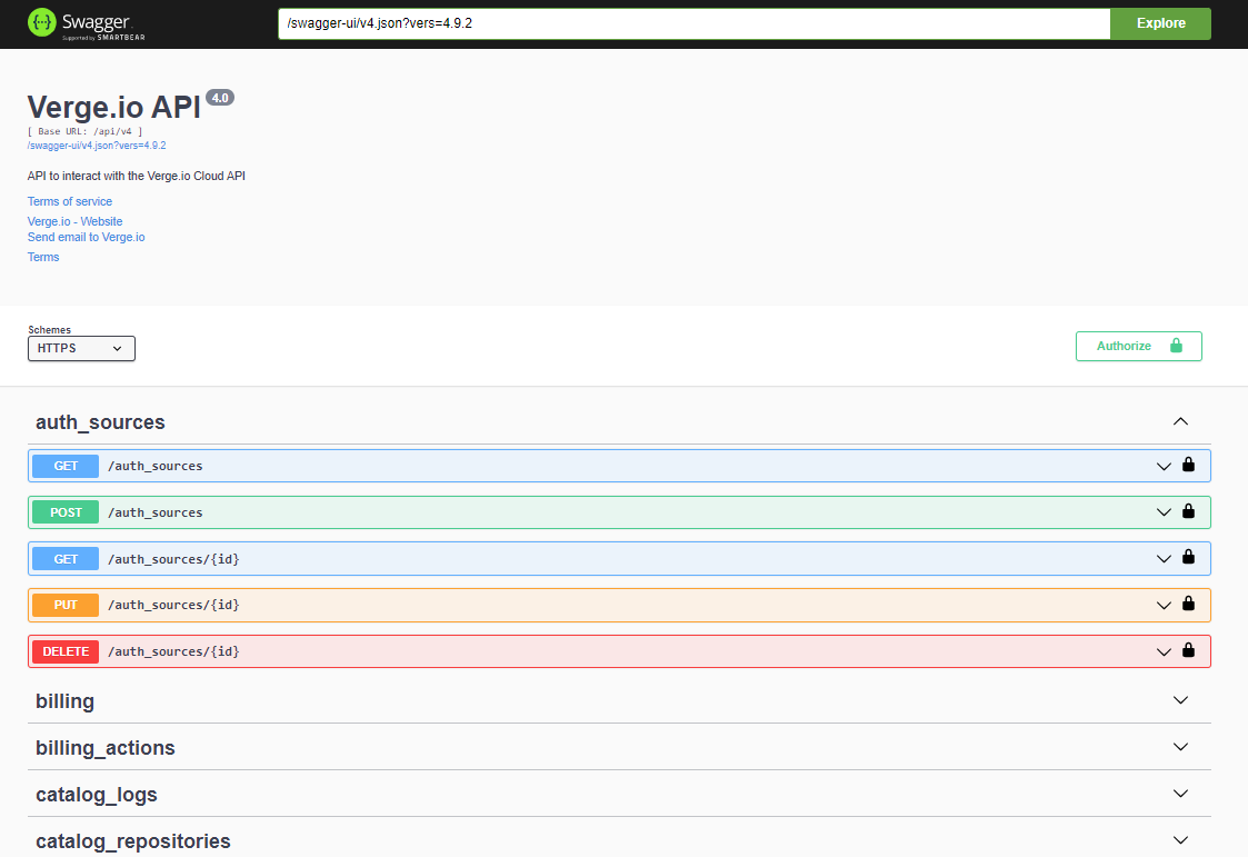
Swagger Documentation Example

  1. Select an individual table and choose one of the available GET/POST/DELETE/PUT options to view and test API actions.

  2. Specify the parameters and click the Execute Button to run the API command. This will return the response, which includes the response body, header, and a curl example.

API Basics

HTTP Methods

The VergeOS API uses standard HTTP methods like GET, POST, PUT, and DELETE for resource manipulation.

GET Parameters

  • fields: Specify which fields to return in the result set.
  • filter: Filter the result set based on certain criteria.
  • sort: Sort the results by a specified field.
  • limit: Limit the number of returned results.

Authentication

All API requests must be made over HTTPS and require authentication using basic access authentication or a session token.

Additional Notes

  • Rate Limits: The API supports a maximum of 1000 requests per hour per API key.
  • Data Formats: All responses are returned in JSON format.
  • Pagination: Endpoints that return large sets of data support pagination using offset and limit query parameters.

Authentication

VergeOS supports two methods of authentication:

  1. Basic HTTP Authentication
    The API is available only through SSL.

  2. Token-based Authentication
    Developers must request a token from the API by posting to the /sys/tokens endpoint. The token is then passed in subsequent API requests in the x-yottabyte-token header.

Example Authentication Request

To obtain a token:

curl --header "X-JSON-Non-Compact: 1" --basic --data-ascii '{"login": "USERNAME", "password": "PASSWORD"}' --insecure --request "POST" --header 'Content-Type: application/json' 'https://your-verge-instance.com/api/sys/tokens'

Example response:

{
   "location":"\\/sys\\/tokens\\/3a334563456378845634563b7b82d2efcadce9",
   "dbpath":"tokens\\/3a334563456378845634563b7b82d2efcadce9",
   "$row":1,
   "$key":"3a334563456378845634563b7b82d2efcadce9"
}

Use the token from the "$key" field in all subsequent requests:

x-yottabyte-token: 3a334563456378845634563b7b82d2efcadce9

To log out, send a DELETE request to the /sys/tokens/{token} endpoint.

Example Logout Request

DELETE /sys/tokens/3a334563456378845634563b7b82d2efcadce9

Example Virtual Machines

The VMs section of the VergeOS API allows users to manage virtual machines programmatically. It includes endpoints to list, create, modify, and delete VMs.

Retrieve a List of Virtual Machines

Endpoint:
GET /v4/vms?fields=most

Description:
Retrieves a list of all VMs in the system with details such as CPU cores, RAM, machine type, and configuration details.

Example Request:

curl -X 'GET' \
  'https://your-verge-instance.com/api/v4/vms?fields=most' \
  -H 'accept: application/json' \
  -H 'x-yottabyte-token: <your-token>'

Example Response:

[
  {
    "$key": 1,
    "name": "CentOS 7 (Latest) 1.0-7",
    "machine": 7,
    "cpu_cores": 2,
    "cpu_type": "Cascadelake-Server",
    "ram": 2048,
    "os_family": "linux",
    "is_snapshot": true,
    "boot_order": "cd",
    "rtc_base": "utc",
    "console": "vnc",
    "uefi": false,
    "secure_boot": false,
    "serial_port": true,
    "uuid": "d3914756-4ec5-9dfe-5c45-b28af2fd3d73",
    "created": 1724435418,
    "modified": 1724435418
  }
]

Overview of the Data Returned:

  • $key: The unique identifier for the VM.
  • name: The name of the virtual machine.
  • machine: Machine ID associated with the VM.
  • cpu_cores: Number of CPU cores allocated to the VM.
  • ram: Amount of RAM allocated (in MB).
  • os_family: Operating system type.
  • uuid: Universally unique identifier (UUID) for the VM.
  • created: The creation timestamp.
  • modified: The last modified timestamp.

Create a New Virtual Machine

Endpoint:
POST /v4/vms

Description:
Creates a new virtual machine with specific configuration details, such as CPU cores, RAM, machine type, boot order, etc.

Example Request:

curl -X 'POST' \
  'https://your-verge-instance.com/api/v4/vms' \
  -H 'accept: application/json' \
  -H 'x-yottabyte-token: <your-token>' \
  -H 'Content-Type: application/json' \
  -d '{
    "name": "rest",
    "description": "test",
    "machine_type": "pc-q35-9.0",
    "allow_hotplug": true,
    "cpu_cores": 1,
    "cpu_type": "Broadwell",
    "ram": 1024,
    "os_family": "linux",
    "boot_order": "cd",
    "uefi": false,
    "note": "test vm"
  }'

Example Response:

{
  "location": "/v4/vms/36",
  "dbpath": "vms/36",
  "$row": 36,
  "$key": "36"
}

Overview of the Data Returned:

  • location: The location of the newly created VM resource.
  • dbpath: Database path of the new VM.
  • $row: Row ID of the VM.
  • $key: Unique key for the VM.

Example Virtual Networks (Vnets)

The Vnets section of the VergeOS API allows users to manage virtual networks (Vnets) programmatically. It includes endpoints to retrieve, create, and manage network resources, including internal and external networks, and allows advanced options like rate limiting.

Retrieve Vnet Details

Endpoint:
GET /v4/vnets?fields=most

Description:
Retrieves a list of all Vnets in the system with details such as network type, MTU, DHCP settings, and DNS configuration.

Example Request:

curl -X 'GET' \
  'https://your-verge-instance.com/api/v4/vnets?fields=most' \
  -H 'accept: application/json' \
  -H 'x-yottabyte-token: <your-token>'

Example Response:

[
  {
    "$key": 6,
    "name": "Internal Test 1",
    "advanced_options": {
      "dnsmasq": [
        "--dhcp-boot=netboot.xyz.kpxe,,192.168.10.20",
        "--dhcp-match=set:efi-x86,option:client-arch,6",
        "--dhcp-boot=tag:efi-x86,netboot.xyz.efi,,192.168.10.20",
        "--dhcp-match=set:efi-x86_64,option:client-arch,7",
        "--dhcp-boot=tag:efi-x86_64,netboot.xyz.efi,,192.168.10.20",
        "--dhcp-match=set:efi-x86_64,option:client-arch,9",
        "--dhcp-boot=tag:efi-x86_64,netboot.xyz.efi,,192.168.10.20"
      ]
    },
    "type": "internal",
    "layer2_type": "vxlan",
    "network": "192.168.100.0/24",
    "mtu": 9000,
    "dhcp_enabled": true,
    "dhcp_start": "192.168.100.100",
    "dhcp_stop": "192.168.100.200",
    "rate_limit": 0,
    "rate_limit_type": "mbytes/second",
    "gateway": ""
  }
]

Overview of the Data Returned:

  • $key: The unique identifier for the Vnet.
  • name: Name of the virtual network.
  • advanced_options: Advanced options to be passed to services running inside the network, in this example netboot flags for dnsmasq
  • type: Network type (e.g., "internal").
  • layer2_type: The type of Layer 2 networking, such as VXLAN.
  • network: Network CIDR block.
  • mtu: Maximum Transmission Unit (MTU) size.
  • dhcp_enabled: Indicates whether DHCP is enabled for this network.
  • dhcp_start: Starting IP address for the DHCP pool.
  • dhcp_stop: Ending IP address for the DHCP pool.
  • rate_limit: Rate limit for the network (in mbytes/second).
  • gateway: The default gateway for the network.

Create an Internal Network with Rate Limiting

Endpoint:
POST /v4/vnets

Description:
Creates a new internal virtual network with rate limiting and DHCP settings.

Example Request:

curl -X 'POST' \
  'https://your-verge-instance.com/api/v4/vnets' \
  -H 'accept: application/json' \
  -H 'x-yottabyte-token: <your-token>' \
  -H 'Content-Type: application/json' \
  -d '{
    "name":"int1",
    "description":"workloads",
    "type":"internal",
    "mtu":"9000",
    "network":"192.168.80.0/24",
    "gateway":"192.168.80.1",
    "dnslist":"1.1.1.1",
    "dhcp_enabled": true,
    "rate_limit": 100,
    "rate_limit_burst": 500,
    "dhcp_start":"192.168.80.100",
    "dhcp_stop":"192.168.80.200"
  }'

Example Response:

{
  "location": "/v4/vnets/8",
  "dbpath": "vnets/8",
  "$row": 8,
  "$key": "8"
}

Overview of the Data Returned: - location: The location of the newly created Vnet resource. - dbpath: Database path of the new Vnet. - \(row**: Row ID of the Vnet. - **\)key: Unique key for the Vnet.


Resources

Below is an example URL used to query a list of machines.

Example: https://user1:xxxxxx@server1.verge.io/api/v4/machines?fields=all

https:// user : password @ server /api /v4/machines ? filter=&fields=all&sort=&limit=
User name User Password Server host name or IP Resource location (URI) These options are described below

GET Options

Fields
  • Specify which fields to return in the result set (may also be a view if there is one defined for the table schema).
  • all returns every field.
  • most returns most fields except for argument fields and rows.
  • summary returns fields marked as 'summary' in their schema.
  • Example: fields=name,email,enabled,groups[all] as all_groups,collapse(groups[name]) as first_groups_name

Field functions: - collapse - datetime - upper - lower - count - diskspace - display - hex - sha1 - sum - avg - min - max

Filter
  • Filter result sets by specified criteria.
  • Similar to OData.
  • Example: filter=enabled eq true and size gt 1048576.
  • Example: filter=cputype eq 'qemu' or cputype eq 'kvm'.
Operator Description
eq Equal
ne Not equal
gt Greater than
ge Greater than or equal
lt Less than
le Less than or equal
bw Begins with
ew Ends with
and Logical and
or Logical or
cs Contains string (case sensitive)
ct Contains text (case insensitive)
rx Regex match
Sort
  • Sort results by the specified field.
  • Example: sort=+name.
  • Example: sort=-id.
Limit
  • limit (integer) limits the result set to a specified number of entries. A value of 0 means unlimited.
  • Example: limit=1.

Generic HTTP Response Codes

  • 400 - Bad Request: The request was invalid.
  • 401 - Failed Login / Login Required: Authentication failed or is required.
  • 403 - Permission Denied: You lack the required permissions.
  • 404 - Resource Not Found: The requested row or API does not exist.
  • 405 - Not Permitted: The operation is not allowed.
  • 409 - Row Exists: The resource already exists.
  • 422 - Failed Validation / Invalid Parameter: Validation failed.
  • 500 - Internal Server Error: An unhandled error occurred.
POST-Specific
  • 201 - Created: A new row/resource was successfully created.
Websocket-Specific (Used for VNC/SPICE)
  • 101 - Switching Protocols: The protocol was successfully switched.
PUT/GET/DELETE
  • 200 - Success: The operation completed successfully.

Schema Table Definitions

Field Types
  • bool
  • text
  • string
  • num
  • uint8
  • uint16
  • uint32
  • uint64
  • int8
  • int16
  • int32
  • int64
  • enabled
  • created
  • created_ms
  • created_us
  • modified
  • modified_ms
  • modified_us
  • filename
  • filesize
  • fileused
  • fileallocated
  • filemodified
  • json
  • row
  • rows
Schema Owner / Parent Field
  • Owner Field: If the owner field is null, normal permissions apply. If the owner field has a value, permissions are replaced by a permission check to the owner.
  • Parent Field: The permission check is applied to the row itself, and if permissions fail, permissions are also checked on the parent row.

Full Table Schema

To retrieve a table’s schema, append $table to the URI:

/api/v4/machines/$table (replace "machines" with the table name).

You will be prompted for your credentials; this requires VergeOS admin credentials. The output will be in JSON format. Firefox displays this in a readable format by default, but other browsers may require exporting the JSON to an external program for better readability.


Example Errors

Example Error (HTTP Code 422)
{
  "err": "Validation error on field: 'dhcp_start' - 'fails validation test'"
}

VergeOS uses standard HTTP status codes to indicate the result of an API request.

  • 400 Bad Request: The request is invalid or cannot be processed.
  • 401 Unauthorized: The API key is missing or invalid.
  • 403 Forbidden: The API key lacks the required permissions.
  • 404 Not Found: The resource does not exist.
  • 500 Internal Server Error: A server error occurred.

Document Information

  • Last Updated: 2024-11-14
  • vergeOS Version: 4.12.6

Terraform VergeIO Provider

The Terraform VergeIO Provider enables the integration and automation of VergeOS infrastructure with Terraform. It allows users to define, manage, and scale VergeOS resources as part of Infrastructure as Code (IaC) workflows.

For the latest provider documentation and examples, please refer to the following:


Example Usage

For more detailed usage examples, check the docs folder in the GitHub repository.

Example Configuration

provider "vergeio" {
  host     = "https://some_url_or_ip"
  username = "my_user"
  password = "my_password"
  insecure = false  # Use true if using self-signed SSL certificates
}

resource "vergeio_vm" "new_vm" {
  name        = "NEW VM"
  description = "NEW TF VM"
  enabled     = true
  os_family   = "linux"
  cpu_cores   = 4
  machine_type = "q35"
  ram         = 8192
}

Initializing and Applying

To apply the configuration:

terraform init && terraform apply

Configuration Reference

host (Required): URL or IP address for the VergeOS system or tenant.
username (Required): Username for the VergeOS system or tenant.
password (Required): Password for the provided username.
insecure (Optional): Set to true for systems using self-signed SSL certificates.

Resources

The following VergeOS resources can be managed via Terraform:

vergeio_drive
vergeio_member
vergeio_network
vergeio_nic
vergeio_user
vergeio_vm

Data Sources

The following data sources are available for querying VergeOS resources:

vergeio_clusters
vergeio_groups
vergeio_mediasources
vergeio_networks
vergeio_nodes
vergeio_version
vergeio_vms

Testing a Sample Configuration

To test your configuration, create a main.tf file in your Terraform workspace:

terraform {
  required_providers {
    vergeio = {
      source = "vergeio/cloud/vergeio"
    }
  }
}

provider "vergeio" {
  host     = "https://someURLorIP"
  username = "username"
  password = "password"
}

resource "vergeio_vm" "new_vm" {
  name        = "NEW VM"
  description = "NEW TF VM"
  enabled     = true
  os_family   = "linux"
  cpu_cores   = 4
  machine_type = "q35"
  ram         = 8192
}

Then, run the following command:

terraform init && terraform apply

Document Information

  • Last Updated: 2024-09-03
  • VergeOS Version: 4.12.6

Updating a VergeOS System with Airgap License

Overview

Key Points

  • System updates should be performed during a maintenance window
  • This guide details the process of manually updating a VergeOS system using an air-gap license.
  • The update is performed using an ISO file, ensuring that systems without internet access can be kept up-to-date.
  • Ensure you have a valid air-gap license and the latest ISO file before starting.

This guide provides a step-by-step process to manually update your air-gapped VergeOS system using an ISO file.

Prerequisites

  • Access to the VergeOS Cloud Dashboard.
  • The latest VergeOS update ISO file.
  • A valid air-gap license.
  • A recent backup of your VergeOS system.

Steps

  1. Download the Update ISO - Visit the VergeOS updates page at https://updates.verge.io/download. - Download the latest VergeOS release ISO file.

!!! tip "Pro Tip" Ensure that the ISO file corresponds to your current VergeOS version to avoid compatibility issues.

  1. Upload the ISO to VergeOS - Log in to your VergeOS Cloud Dashboard. - Navigate to Media Images in the left-hand menu. - Upload the downloaded ISO file to the Media Images section.

!!! note The upload process may take a few minutes depending on your network speed.

  1. Configure Update Settings - Go to System > Updates > Edit Settings. - In the Update Source dropdown menu, select -- Update ISO --. - Choose the ISO file you just uploaded from the Media Images. - Click Submit to save the settings.

  2. Perform the Update - Return to the Updates section and click Check For Updates. - Once the update is detected, click Download. - After the download completes, click Install. - Follow the prompts to Reboot the system to apply the updates.

!!! warning "Important" Do not interrupt the update process. Ensure that the system remains powered on and connected during the update.

Troubleshooting

Common Issues

  • Issue: Update not detected after uploading the ISO.
  • Solution: Ensure the ISO was uploaded correctly and reselect it in the Update Source settings.

  • Issue: Errors during the update process.

  • Solution: Check system logs for detailed error messages and verify that your air-gap license is valid.

  • Issue: System fails to reboot after the update.

  • Solution: Contact Verge support for assistance.

Additional Resources

Feedback

Need Help?

If you encounter any issues during the update process or have any questions, please reach out to our support team.


Document Information

  • Last Updated: 2024-08-19
  • VergeOS Version: 4.12.6

Requesting an Airgap License for VergeOS

Air-gap licensing is not common and requires justification. Please see Licensing and Software Updates for more information.

Overview

Key Points

  • VergeOS requires a valid license for operation
  • Air-gapped environments need a special airgap license
  • The process involves generating a license request file and emailing it to Verge

This guide walks you through the process of requesting an airgap license for VergeOS systems in environments without outbound Internet access.

Prerequisites

  • Access to the VergeOS Cloud Dashboard
  • A working email client on a machine that can send external emails
  • Understanding of your system's airgapped status

Steps

  1. Navigate to System Settings

    • From the System Dashboard, click System on the left menu
    • Click Settings on the left menu
  2. Initiate License Request

    • In the License section, click the Request License button
  3. Generate License Request File

    • A popup window titled "Request Generated" will appear
    • This window displays information about the license request file
  4. Download Request File

    • Click the Download Request File button
    • Save the license request file to your local machine
  5. Prepare Email to Verge

    • Click the Email license@Verge.io button
    • This opens your default email client with a pre-addressed email
  6. Send License Request

    • Attach the downloaded license request file to the email
    • Provide additional information in the email body (e.g., company name, purpose of license)
    • Send the email to Verge's licensing team

What Happens Next

  1. Verge processes your request and generates an airgap license file
  2. You receive a reply email with the airgap license file attached
  3. Upload the received license file to your VergeOS system (covered in a separate guide)

Processing Time

If you haven't received a response within 2 business days, please follow up with Verge's support team.

Important Considerations

  • Ensure the system requesting the license is the one you intend to license
  • Keep the license request file secure
  • For multiple systems, repeat this process for each system individually

Troubleshooting

Common Issues

  • Problem: Unable to generate license request file
  • Solution: Verify your access permissions in the VergeOS Cloud Dashboard

  • Problem: Email client doesn't open automatically

  • Solution: Manually compose an email to license@Verge.io and attach the downloaded request file

Feedback

Need Help?

If you encounter any issues while requesting an airgap license or have questions about this process, please don't hesitate to contact our support team.


How to Achieve Network Micro-Segmentation on VergeOS

Network micro-segmentation is a security approach that divides a network into isolated segments, each with its own security controls. This article explains how to implement micro-segmentation using VergeOS's powerful networking features.

Key Features for Micro-Segmentation

VergeOS provides several features that enable effective network micro-segmentation:

  1. Internal Networks: Create multiple isolated virtual networks.
  2. Network Rules: Implement granular firewall rules.
  3. IPSec and WireGuard VPNs: Establish encrypted tunnels between networks.
  4. Tenant Isolation: Separate virtual data centers for strong multi-tenancy.
  5. Network Aliases: Group IP addresses/networks for easier policy management.
  6. Port Mirroring: Monitor traffic for security analysis.

Implementing Micro-Segmentation

Follow these steps to achieve network micro-segmentation on VergeOS:

1. Design Your Network Topology

  • Create separate internal networks for different applications or workloads.
  • Each internal network provides a default-secure environment.

Example:

- Web Application Network
- Database Network
- Management Network
- Development Network

2. Configure Network Rules

Use network rules to control traffic between internal networks and VMs:

  1. Navigate to the network dashboard.
  2. Select "Rules" from the left menu.
  3. Click "New" to create a rule.
  4. Set the action (e.g., Accept, Drop), protocol, and direction.
  5. Define source and destination networks/IPs.
  6. Apply the rule.

Example rule: Allow web servers to access the database on a specific port:

Action: Accept
Protocol: TCP
Direction: Outgoing
Source: Web Application Network
Destination: Database Network
Destination Port: 3306

3. Utilize Network Aliases

Group IP addresses or networks for easier policy management:

  1. Go to the network dashboard.
  2. Select "Aliases" from the left menu.
  3. Click "New" to create an alias.
  4. Name the alias and add IP addresses or networks.
  5. Use the alias in network rules.

Example:

Alias Name: Web Servers
IP Addresses: 192.168.1.10, 192.168.1.11, 192.168.1.12

4. Implement VPN Tunnels

For sensitive traffic between networks, use IPSec or WireGuard VPNs:

  1. Navigate to the VPN configuration section.
  2. Choose IPSec or WireGuard.
  3. Configure the VPN settings (e.g., encryption, authentication).
  4. Apply the VPN to the desired networks.

5. Leverage Tenant Isolation

For multi-tenant environments:

  • Create separate tenants for different departments or customers.
  • Each tenant has its own set of isolated internal networks.

6. Monitor and Adjust

Use port mirroring to monitor traffic:

  1. Go to the network dashboard.
  2. Enable port mirroring for the networks you want to monitor.
  3. Analyze the traffic and adjust network rules as needed.

Best Practices

  • Follow the principle of least privilege: only allow necessary traffic.
  • Regularly review and update network rules.
  • Use descriptive names for networks, rules, and aliases.
  • Document your network topology and segmentation strategy.

By utilizing these features and following these steps, you can create a highly segmented network architecture on VergeOS, implementing zero trust principles and reducing the potential attack surface.


Document Information

  • Last Updated: 2024-08-29
  • vergeOS Version: 4.12.6

API Helper Script

The yb-api helper script provides an easy way for developers to interact with the VergeOS API. It simplifies making API calls, such as retrieving virtual machines, updating configurations, and managing resources. This guide will outline the key commands and usage of the yb-api script.

Prerequisites

  • Access to a VergeOS system.
  • Access to the cluster via SSH or direct connection.
  • wget and curl must be installed on the system for certain operations.

Running the Helper Script

To get help or view the available options, run:

yb-api --help

Connect to the node and execute this command to begin using the API helper.

yb-api Example

Example Commands

Below are examples of how to use yb-api for various VM management tasks.

Get a List of Virtual Machines (excluding snapshots)

Retrieve a list of VMs and filter out snapshots.

yb-api --get --user=admin --server=10.0.0.100 \
--fields='name,$key,ram,machine#status#status as machine_status' \
--filter='is_snapshot eq false' /v4/vms

Simple Dump of All VMs

This command retrieves a list of all VMs. The --server, --user, --filter, and --fields flags are optional in this case.

yb-api --get /v4/vms

Get Detailed VM Information

Retrieve most of the fields, including drive and NIC information, for a specific VM (VM 1 in this case).

yb-api --get --user=admin --server=10.0.0.100 \
--fields='most,machine[most,drives[most],nics[most]]' /v4/vms/1

Rename a Virtual Machine

Change the name of an existing virtual machine (VM 1) to "NEWNAME".

yb-api --put='{"name":"NEWNAME"}' --user=admin --server=10.0.0.100 /v4/vms/1

Delete a Virtual Machine

Delete a specific VM (VM 1), using its $key.

yb-api --delete --user=admin --server=10.0.0.100 \
--fields='name,$key,ram' /v4/vms/1

Create a New Virtual Machine

Create a new VM with specific configurations (name, CPU cores, RAM, etc.).

yb-api --post='{"name":"NEWVM","enabled":true,"description":"test vm",\
"os_family":"linux","cpu_cores":4,"ram":"8192"}' --user=admin \
--server=10.0.0.100 /v4/vms

Get the VM Database Table Schema

Retrieve the schema for the VMs database table.

yb-api --get --user=admin --server=10.0.0.100 '/v4/vms/$table'

Clone a Virtual Machine

Clone an existing VM (VM 1) and give it a new name.

yb-api --get --user=admin --server=10.0.0.100 '/v4/vm_actions' \
--post='{"vm":1, "action": "clone", "params": {"name": "NEW VM NAME"}}'

Power On a Virtual Machine

Power on an existing VM (VM 1).

yb-api --get --user=admin --server=10.0.0.100 '/v4/vm_actions' \
--post='{"vm":1, "action": "poweron"}'

Notes About yb-api

  • The yb-api script relies on wget, which may not be installed by default on macOS. Make sure to install it if necessary.
  • curl is used for the upload function in certain API calls, such as posting data to create new VMs.

By using the yb-api helper script, developers can simplify interaction with the VergeOS API and manage virtual machines more efficiently. Let us know if you need assistance with further commands or options.


Document Information

  • Last Updated: 2024-08-29
  • vergeOS Version: 4.12.6

Max RAM per machine setting explained

The Max RAM per machine setting determines the maximum amount of RAM that a virtual machine can utilize on a particular cluster. This setting helps prevent a single VM from consuming excessive resources and affecting the cluster's overall performance.

At the time of installation, the default maximum RAM setting is 64GB. To run a virtual machine requiring more than 64GB, this setting must be adjusted. Fortunately, changes can be made at runtime, so a node reboot is not required to apply the updated setting.

If a VM attempts to use more RAM than allowed by the cluster, an error message, "Machine exceeds the max amount of RAM allowed on this cluster", will be logged. To resolve this, adjust the setting to accommodate the workload.

Adjusting the Max RAM per machine setting

Follow these steps to adjust the setting:

  1. From the Main Dashboard, navigate to System and then Clusters in the left-hand menu, or select the Clusters count box in the top row.
  2. In the Cluster list view, select the cluster where the virtual machine is set to run.
  3. Select Edit in the left-hand menu.
  4. Adjust the Max RAM per machine setting to accommodate the virtual machine's requirements.
  5. Submit the changes by clicking Submit at the bottom of the page.
  6. Start the virtual machine to confirm the changes.

By increasing the Max RAM per machine setting, larger VMs can be successfully launched on the cluster.


Document Information

  • Last Updated: 2024-08-29
  • vergeOS Version: 4.12.6

Configuring Proxy

Using a Proxy grants the ability to use 1 IP address for multiple Tenant environments by mapping FQDN hostnames. This bypasses the need to have 1 IP address per tenant and helps to preserve ipv4 addresses.

Enabling Proxy

  1. From the external network used to access tenant environments: - Select Edit in the left menu. - Enable Proxy. - In most cases, the Proxy Listen Address field can be left blank. This will default to 0.0.0.0, meaning it will listen on all addresses.

For VergeOS verions 4.12.6 and older

'Bind DNS' will need to be temporarily enabled if it is not already in use on the network. This will expose the IP Alias selection in the UI (step 2).

  • Submit the settings but DO NOT RESTART THE NETWORK OR APPLY RULES YET!
  1. From the same external network: - Select IP Addresses in the left menu. - Edit or create an IP Address, setting the Type to IP Alias. - Submit. - Set the external network DNS back to the original setting (Prior to Version 4.12.4). - Select Rules. - Create a new rule that looks like the following image:

proxy_accept_rule.png

  • Restart the network and apply the rules.
  • Test the rule by opening a browser tab and navigating to the URL using the IP Alias address assigned in the previous step. If it works properly, the UI login page will open on the IP Alias address.

Creating a New Tenant with Proxy

  1. Create an A Record for the new tenant in your domain registrar to point to the assigned IP Alias.
  2. Create a new tenant: - Enter all desired settings, leaving the URL blank.
  3. In the UI Management tab of the tenant creation page, select Create a new FQDN.
  4. In the Proxy Tenant Config page: - Select the network the proxy service is running on. - Select the tenant name. - Enter the FQDN of the tenant (the A Record created in step 1). - Submit.
  5. Select Skip at the bottom of the UI Management page to avoid assigning an IP directly to the tenant.

A tenant cannot have a UI IP address AND a proxied FQDN.

  1. In the new tenant dashboard, select Apply Proxy in the highlighted warning.

  2. Start the tenant and navigate to its URL in a browser tab to log in.

Editing an Existing Tenant to use Proxy

  1. Create an A Record for the tenant in your domain registrar to point to the assigned IP Alias (if one does not already exist).
  2. From the tenant dashboard, select Edit in the left menu: - In the UI Address field, select None.
  3. Navigate to the network running the proxy service: - Select Proxy in the left menu.
  4. From the Proxy Dashboard: - Select View Tenants. - Select New.
  5. In the Proxy Tenant Config page: - Select the network the proxy service is running on. - Select the tenant name. - Enter the FQDN of the tenant (the A Record created in step 1).
  6. Navigate to the tenant dashboard and select Apply Proxy in the highlighted warning.

  7. Select the tenant network (highlighted) from the tenant dashboard.

tenant_apply_rules.png

  1. Select Apply Rules in the highlighted warning.

  2. Test access to the tenant by navigating to its URL in a browser tab.


Document Information

  • Last Updated: 2024-08-29
  • vergeOS Version: 4.12.6

Importing Windows Server with UEFI into VergeOS

This guide covers how to migrate a Windows Server VM with UEFI enabled from VMware into VergeOS. The process was tested with Windows Server 2019 and 2022, but it may also work for earlier versions of Windows.

VMware tools were removed before the migration. This was tested on Windows Server 2019 and 2022. It may also work on previous versions of Windows.

Steps to Import the Windows Server VM

  1. Import the VM from the VMware service. Follow the steps from this guide to import the VM into VergeOS.

  2. Set the primary disk interface to SATA for compatibility during initial boot.

  3. Change the primary disk's Boot Order to 0 in VergeOS.

  4. Power On the VM to boot into Windows.

  5. Install the virtio-win-guest-tools.exe if it's not already installed. This package includes Virtio drivers necessary for disk and network performance.

  6. Once the installation is complete, Power Off the VM.

  7. Delete the EFI drive, as it is no longer needed after the migration. You can remove it from the VM's disk settings.

  8. Change the primary disk interface from SATA to Virtio-SCSI for optimal performance.

  9. Remove the media file (ISO) from the CD drive in the VM settings.

  10. Change the NIC driver to Virtio to ensure the VM uses a high-performance network driver.

  11. Enable the QEMU Guest Agent on the VM edit screen to allow VergeOS to gather information about the VM.

  12. Power On the VM again and ensure everything is working correctly.

  13. Verify that the guest agent is reporting back to VergeOS by checking the VM dashboard.

Monitoring the Guest Agent

The guest agent status can be viewed on the VM's dashboard. If it doesn't report back, ensure the guest agent service is running inside the VM.


Document Information

  • Last Updated: 2024-08-29
  • vergeOS Version: 4.12.6

Generating System Diagnostics

How to Generate System Diagnostics

VergeOS support may request that a system administrator generate a system diagnostics file for detailed logs from the platform. The diagnostic file will include detailed logs from all nodes in a system and package it into a single compressed file which can easily be then uploaded to support automatically or downloaded to be sent via email or a 3rd party file-sharing service.

Here are the steps to create and download a System Diagnostics file. 1. Log in to the parent/root environment. The diagnostics file needs to be generated at the Parent environment, rather than a Tenant. 1. From the Main dashboard, in the left navigation menu, click System 1. On the System dashboard, in the left navigation menu, click System Diagnostics 1. From the System Diagnostics, in the left navigation menu, click Build

  1. Once inside the New System Diagnostic Report, complete the Name, Description, and check the "Send diagnostic information to VergeOS support, then click Submit at the bottom. This will generate a compressed file of system logs.
  2. Wait while the compressed log file is built. The status column will show the status as 'Building" then on to 'Sending to Support'.
  3. When it is finished, the status will change to 'Sent to Support'.
  4. When sending completes, you can also download the file to your local computer.

Document Information

  • Last Updated: 2024-08-29
  • vergeOS Version: 4.12.6

How to Configure a VM Export Volume

In VergeOS, you can create a volume specifically for exporting selected virtual machines (VMs). This export volume can then be used with third-party backup software to back up the VMs. The volume contains VM snapshots from the most recent export.

Steps to Configure a VM Export Volume

1. Preparing the VMs for Export

  1. Edit the VMs you want to export:
    • Navigate to the VM settings and enable the option for Allow Export.

2. Setting Up the NAS Service

To host the VM export volume, you will need to create and configure a NAS service:

  1. Navigate to NAS > NAS Services.
  2. Click New.
  3. Provide Name, Hostname, TimeZone, and Networking for the NAS service.
  4. Click Submit to initialize the NAS service.

3. Starting the NAS Service

Once the NAS service is created:

  1. Select the NAS service from the list.
  2. Click Power On to bring the NAS online and prepare it to host the export volume.

4. Creating a NAS User

You’ll need to create a user to access the NAS:

  1. Navigate to NAS > NAS Services > The NAS Service you created.
  2. Click NAS Users > New.
  3. Provide a username and password.

5. Creating a New Volume for VM Export

  1. Navigate to NAS > Volumes > New
  2. Provide a Name for the volume and choose VergeOS VM Export as the filesystem type.
  3. Select the appropriate NAS service to host the export volume.
  4. Make sure Quiesced is checked.
  5. Adjust the number of exports to store.
  6. Click Submit.

6. Starting the VM Export

  1. Under Export VMs, select Start to initiate the VM export process.
  2. Confirm by clicking Yes at the prompt.

Setting up a CIFS Share for the Exported Data

To access the exported VM snapshots, set up a CIFS share on the NAS volume:

  1. Create a CIFS Share: - Navigate to NAS > CIFS Shares > New. - Select the export volume you created earlier as the target volume. - Provide a Share Name and assign the NAS user you created in step 4 to access the share.

  2. Access the Share: - Browse to \\IPorDNSnameoftheNAS\CIFSShareYouCreated. - Use the NAS user credentials when prompted.

!!! note "For Windows Users" You may need to edit the Group Policy (GPO) or modify the Windows Registry to connect using the Guest account if Guest mode is enabled.

Automating the VM Export

You can schedule regular exports by setting up an automated event:

  1. Navigate to the VM Export Volume.
  2. Select Events > New.
  3. Select *Scheduled as the Task Triggered by.
  4. Provide a Name for the task.
  5. Select VM Exports for section.
  6. Ensure VM Exports as the volume you created previously.
  7. Configure the event to trigger the export at your desired intervals.
  8. Click Submit

By following these steps, you'll have a properly configured VM export volume that can be used with third-party backup solutions, along with automated export scheduling.


Document Information

  • Last Updated: 2024-08-29
  • vergeOS Version: 4.12.6

Importing Physical Machines/Cross Platform VMs into VergeOS

The VergeOS Clone Utility (VergeOS-clone.iso) can be used to import external physical or virtual machines into VergeOS as virtual machines. This process is optimized for PtoV (physical-to-virtual) and non-VMware VtoV (virtual-to-virtual) migrations using efficient block transfer.

For VMware environments, use the VMware connector instead of the VergeOS Clone Utility.

Prerequisites

VergeOS System (Destination)

  • Network URL accessible from the source VMs.
  • VergeOS credentials with VM creation permissions.
  • Sufficient available vSAN storage for VM drives.

VergeOS vSAN global deduplication reduces the space requirement by handling zero blocks.

  • Adequate RAM/CPU to run the imported VMs.

Source Machine (Physical or Virtual)

  • Network connection accessible to the VergeOS system.
  • USB/CD-ROM for the VergeOS Clone ISO.
  • At least 1 GB of RAM to boot and run the ISO.

Selecting Sync Method

  • HTTPS Upload: Default method requiring minimal configuration.
  • vSAN-direct Sync: Optimized for LAN connections (requires additional network setup, not recommended for WAN).

vSAN-direct sync is only allowed to the host system, not directly to tenants.

Obtaining the VergeOS Clone Utility

  1. From the Main Dashboard, click Backup/DR on the left menu.
  2. Click Add Clone ISO in the Clone ISO section.
  3. Select the desired public download option for the ISO file.
  4. After the build process completes, download the ISO via the provided link or from the VergeOS UI.

You can make a bootable USB using the Creating Bootable Installation Media guide, substituting the Clone ISO.

Using the VergeOS Clone Utility

  1. Boot the source machine using the VergeOS Clone ISO.
  2. Select Launch Clone Utility.
  3. Choose the NIC to connect to the VergeOS system.
  4. Select DHCP or configure a Static IP.

If using static IP: - Use the arrow keys to navigate between fields. - Press Enter to edit a field and configure the IP, subnet, gateway, and DNS.

  1. Enter the VergeOS system URL and credentials.

Ensure the user has permissions to create VMs.

  1. Confirm the VergeOS connection and proceed.

Clone Utility Configuration

  1. Enter the name for the VM to be created on VergeOS.
  2. Select the disks to be cloned.
  3. Adjust any Advanced Settings:
    • Send Threads: Default = 4. Adjust for high-latency or high-speed connections.
    • MAC addresses: Choose whether to clone existing MAC addresses or generate new ones.

Setting threads too high may degrade performance.

  1. Begin the clone process by selecting Start Clone.

Resuming a Clone

If a clone import fails or is interrupted, boot the source machine from the VergeOS Clone ISO again and resume by selecting the previously used VM name.

Rebuilding the Clone ISO

  1. To rebuild the Clone ISO after updates, go to Backup/DR on the Main Dashboard.
  2. Click Edit Clone ISO and check Force Rebuild.
  3. The rebuild may take a few minutes.

To automate rebuilds after system updates, schedule a task under System > Tasks/Events.

Direct vSAN Network Configuration

The Direct vSAN transfer method can be used for faster cloning over a local network. It is not recommended for WAN connections.

Direct vSAN can only be used to transfer to a root system (not directly to a tenant).

Network Rules Setup

Three networking rules must be created:

Core Network Rule - 14201 PAT Rule

  1. Name: vSAN PAT
  2. Action: Translate
  3. Protocol: TCP
  4. Direction: Incoming
  5. Source: Any / None (default)
  6. Destination Type: Custom
    Custom Filter: ui
    Destination Ports: 14201
  7. Target Type: IP/Custom
    Target IP: ui

UI is a VergeOS keyword that must be entered in lowercase.

Core Network SNAT Rule

  1. Name: vSAN SNAT for Clone Utility
  2. Action: Translate
  3. Protocol: TCP
  4. Direction: Outgoing
  5. Source: Any / None (default)
  6. Destination Type: My Network Address
    Destination Ports: 14201
  7. Target Type: My Router IP

External Network Rule - 14201 PAT Rule

  1. Name: vsan PAT
  2. Action: Translate
  3. Protocol: TCP
  4. Direction: Incoming
  5. Source: Source IP/IP range of the incoming clone transfer
  6. Destination Type: My Router IP
    Destination Ports: 14201
  7. Target Type: IP/Custom
    Target IP: ui

Once the rules are created, click Apply Rules to finalize the configuration.

Troubleshooting Common Issues

Failed DHCP

If DHCP cannot be found:

  • Verify there is an active DHCP service.
  • Ensure network connectivity is available through the selected NIC.

Login Failed

  • Check the username, password, and URL format (no "https://").
  • Verify static IP settings and DNS configuration if using static addressing.

OpenSSL Errors

These errors indicate network problems. Check for MTU mismatches or other network issues.

Permission Denied

Ensure the VergeOS user has the necessary permissions to create VMs.

If the initial clone fails due to permissions, you can resume the process or delete the VM and restart the clone.


Document Information

  • Last Updated: 2024-08-29
  • vergeOS Version: 4.12.6

Wireguard - Setup Remote Access VPN

How to Setup a Wireguard Remote Access VPN

Here are instructions on how to set up a Remote Access VPN using the built-in Wireguard capabilities of VergeOS. More information can be found in the Help section of the VergeOS User Interface.

Create the Wireguard Setup on Your Internal Network

You can use an existing Internal Network or create a new Internal Network.

  1. In the Verge OS UI, navigate to Networks -> Internals and view or double-click on the Internal Network that you want to use.
  2. In the left menu, click on Wireguard (VPN).
  3. Click on Add New Interface. wireguardvpn-img1.png

  4. Enter the following information:

    • Enter a unique Name for this interface.
    • Enter a Description (optional).
    • Check Enabled.
    • Enter the IP Address to be used for this Wireguard Internal Network. This must be separate from your existing Internal network IP scheme. For example, if your Internal Network is using 192.168.0.1/24, you must choose a different unique IP scheme like 192.168.255.1/24.
    • Enter the Listen Port to be used when connecting to the VPN (Default: 51820). This is the port that you will use on your External network to send VPN traffic into your Internal Network.
    • Enter a Private Key or leave it blank to auto-generate a key.
    • Enter an Endpoint IP or leave it blank, and the system will attempt to auto-detect the IP. We highly recommend you enter the IP manually to ensure the correct config. This IP is the external IP of your environment, usually the same IP as your UI. You can find your External IP by going to Networks -> Externals and viewing your External network. In the Network Router section, it should be the IP address as shown below: wireguardvpn-img3-fixed.png
  5. Click Submit to add the new interface.

  6. After adding the interface, it will take you to the dashboard where you will see your new interface.
    wireguardvpn-img2.png

  7. Click Apply Rules on the left menu bar to apply the firewall rules. The rules automatically created will accept inbound UDP traffic on port 51820 to both the Router IP and the DMZ IP of the Internal Network. wireguardvpn-img-intrules.png

External Network PAT Rule

In order for the internal network to be connected, we need an external PAT (Port Address Translation) rule to translate the port (default 51820) to the internal network.

2023-09-06_11_56_18-training___rules.png

Add External PAT Rule
  1. From the External network Dashboard, click Rules on the left menu.
  2. Click New on the left menu.
  3. Enter a Name that will be helpful to future administration.
  4. Optionally, a Description can be entered to record additional administrative information.
  5. In the Action dropdown, select Translate.
  6. In the Protocol dropdown, select UDP.
  7. In the Direction dropdown, select Incoming.

Source:

  1. In the Type dropdown, select Any/None. Optionally, you can source-lock the VPN traffic here if needed.

Destination:

  1. In the Type dropdown, select My Router IP. If you are inside a Tenant, change this to My IP Addresses and choose the IP of the Tenant UI. This should be the same as the Endpoint IP used above. If using a different IP than the UI IP, create an SNAT rule on the External network.

  2. In the Destination Ports/Ranges field, enter the Port (Default Port: 51820).

Target:

  1. In the Type dropdown, select Other Network DMZ IP.
  2. In the Target Network dropdown, select the Target Network.
  3. Leave the Target Ports/Ranges field blank.

  4. Click Submit and Apply Rules on the left menu to put the new rule into effect.

SNAT Rule (if not using UI IP)

If you are adding Wireguard and are not using the IP address of the UI, we recommend creating an SNAT rule on the External network.

  1. From the External network Dashboard, click Rules on the left menu.
  2. Click New on the left menu.
  3. Enter a Name that will be helpful to future administration.
  4. Optionally, enter a Description for additional information.
  5. In the Action dropdown, select Translate.
  6. In the Protocol dropdown, select UDP.
  7. In the Direction dropdown, select Outgoing.

Source:

  1. In the Type dropdown, select Other Network DMZ IP.
  2. In the Network dropdown, select the Internal Network that Wireguard is on.
  3. Leave the Source Ports/Ranges field blank.

Destination:

  1. In the Type dropdown, select Any / None.
  2. Leave the Destination Ports/Ranges field blank.

Target:

  1. In the Type dropdown, select My IP Addresses.
  2. In the IP Address dropdown, select the IP address you want to use.

  3. Click Submit and Apply Rules to enable the SNAT rule.

This SNAT rule forces any outgoing traffic from the DMZ IP of the internal network to use the correct IP. By default, it goes out the UI IP, causing flapping issues.

Adding a Remote User Peer

You will set up a Peer for each user connecting to the VPN.

  1. From the Wireguard Interface screen, click Add new peer. wireguardvpn-img4.png

  2. Assign a Name to the peer, such as the remote user's name.

  3. Optionally, enter a Description.
  4. Check the Auto-Generate Peer Configuration checkbox.
  5. Enter the Endpoint for the Peer (the external-facing IP address, hostname, or URL).
  6. For Allowed IPs, enter the /32 IP for this peer.
  7. In the Configure Firewall dropdown, select Remote User.
  8. Click Submit to save the peer entry. wireguardvpn-img6.png
Download the Configuration File:
  1. Click the Download Config button on the peer record and download the file.

download-link.png configuration-file.png

Install WireGuard Software on Client:

WireGuard client software can be downloaded from: https://wireguard.com/install.

  1. Install WireGuard on the client machine.
  2. Click Add Tunnel.
  3. Navigate to and select the generated configuration file.
  4. Click the Activate button to open the tunnel. tunnel-active.png

Document Information

  • Last Updated: 2024-08-29
  • vergeOS Version: 4.11

Importing VMs from Media Images

Importing via Media Images allows you to import a single VM at a time by uploading VM data files (such as VMX, VMDK, OVF, VHD/X) to VergeOS and then selecting them for import.

Importing a VM (Configuration and Disks) from Media Images

Hyper-V VMs

Hyper-V VMs should be exported to OVA/OVF or VMware formats before upload, or you can use the Create VM Shell, Import VM Disks method described below to create the VM first, and then import disks.

  1. Upload the configuration and disk image files to the vSAN. For instructions, see Managing Media Images.
  2. From the Main Dashboard, click Machines on the left menu.
  3. Click New VM on the left menu.
  4. From the options list, select --Import from Media Images--. The files uploaded to the vSAN will appear on the right under Selections Available. Click to select the VM configuration file (e.g., *.vmx, *.ovf).
  5. Click Next at the bottom of the screen.
  6. The VM Name will default to the name of the configuration file unless you specify a custom name.
  7. By default, the Preserve MAC Address option is selected. If you wish to assign a new MAC address to the VM, deselect this option.
  8. Select the Preferred Tier, or leave it at the default. This specifies the storage tier for the VM's disks. See Preferred Tier Usage for more details.
  9. Click Submit to create the VM. The new VM's dashboard will be presented.

Create VM Shell, Import VM Disks

If you cannot import the entire configuration, you can create a VM shell (a disk-less VM) and then import individual disk files.

  1. Upload the disk image files to the vSAN. See Managing Media Images for details.
  2. Create a new Custom VM with appropriate hardware specifications. See the Creating VMs section in the VergeOS help guide.
  3. Add a new drive to the VM, ensuring to select Import Disk in the Media field.
  4. Choose the correct Interface (IDE, SATA, virtio-scsi, virtio-legacy, etc.). Using SATA often helps with driver compatibility in guest OSs.
  5. Select the Media File from the list of uploaded files (*.vhd, *.vhdx, *.qcow, raw, etc.).
  6. Repeat for additional drives if necessary.
  7. Start the VM and verify that it boots correctly.

Supported File Types

The following file types are supported for VM imports using media images: - IMG (Raw Disk Image) - RAW (Binary Disk Image) - QCOW (Legacy QEMU) - QCOW2 (QEMU, Xen) - VDI (VirtualBox) - VHD/VPC (Legacy Hyper-V) - VHDX (Hyper-V) - OVA (VMware, VirtualBox) - OVF (VMware, VirtualBox) - VMDK (VMware) - VMX (VMware)

Troubleshooting Issues

Failure to Boot into the OS

This is often a driver issue. You may encounter a Windows Inaccessible Boot Device error or similar.

Steps to resolve:

  1. Change the drive interface from virtio-scsi to IDE or SATA. This often resolves driver issues.
  2. Once the guest OS boots, install the virtio drivers by attaching them via a virtual CD-ROM or downloading them from virtio-win.
  3. Shut down the VM.
  4. Switch the drive interface back to virtio-scsi.
  5. Start the VM again.

Document Information

  • Last Updated: 2024-08-29
  • vergeOS Version: 4.12.6

How to Resize a Virtual Disk Drive

Note

Drives can only be increased in size; they cannot be reduced. Verify whether your guest OS supports resizing without a power cycle, particularly for Virtio-SCSI drives.

To resize a virtual disk drive within a VM, follow these steps:

  1. From the VM Dashboard, click Drives in the left menu.
  2. Select the drive to be modified.
  3. Click Edit in the left menu.
  4. Modify the drive size as desired.
  5. Click Submit.

Important Notes

Note

If the VM configuration allows hot-plugging, the disk interface is set to Virtio-SCSI, and the guest Operating System (OS) supports it, the drive size can typically be increased without power cycling the VM.

Warning

Drives cannot be reduced in size. While partitions may be resized inside the guest OS, the disk drive itself cannot be shrunk.

Warning

Modifications to drive size will most likely require corresponding changes within the guest Operating System to utilize the newly added space.


Document Information

  • Last Updated: 2024-08-29
  • vergeOS Version: 4.12.6

Network Blocks

Network Blocks Overview

Network blocks in VergeOS are a powerful way to assign multiple IP addresses to tenants or networks for workloads. This method is preferred over virtual wires since VergeOS focuses on Layer 3 connectivity, avoiding the common issues associated with Layer 2 connections (like virtual wires). Network blocks also allow the direct assignment of public IP addresses to VMs inside an internal network or a tenant.

Creating a Network Block

  1. In the VergeOS UI, navigate to the External Network where the network block will originate.
  2. In the left menu, select Network Blocks, then click New.
  3. Enter the network block information in CIDR notation (e.g., a.b.c.d/n).
  4. To assign the block to a tenant at creation, set the Owner Type to Tenant, then select the tenant from the Owner drop-down.
  5. Submit your work to create the block.
  6. To apply the automatically created rules, select the External breadcrumb in the header to return to the network dashboard. Then, select Apply Rules from the left menu or click the notification pop-up.

Creating a Network from a Network Block

  1. Log in to the tenant's URL with the necessary credentials.
  2. Navigate to Networks, then go to the External Network Dashboard.
  3. In the left menu, select Network Blocks.
  4. Select the network block assigned to the tenant.
  5. Click New Network in the left menu.
  6. Give the new network a name. The rest of the details will be pre-filled based on the CIDR information.
  7. Modify any details in the form if necessary, then submit to create the network.
  8. After creation, the system will redirect you to the new network's dashboard. The necessary routes and accept rules will be set up automatically, but note that inbound traffic will be dropped by default. Add appropriate firewall rules to allow inbound access.
  9. Power on the network using the option in the left menu.
  10. Assign any desired virtual machines to the network and test connectivity.

Document Information

  • Last Updated: 2024-08-29
  • vergeOS Version: 4.12.6

Changing Resolution on a UEFI VM

In a UEFI-based virtual machine (VM), the screen resolution is controlled by the OVMF (Open Virtual Machine Firmware) Platform Configuration. By default, only the resolution configured in the platform settings is available to the VM. If you need to change the display resolution, follow the steps outlined below.

Steps to Change the Screen Resolution

  1. Reboot the VM while connected to the console (through the VergeOS UI or any console manager you're using).

  2. As the VM starts, press ESC to enter the UEFI Settings menu.

  3. Once in the UEFI menu, navigate to Device Manager.

  4. In Device Manager, select OVMF Platform Configuration.

  5. Choose your desired Preferred Resolution from the list of available options.

  6. Save the configuration changes and reboot the VM for the new resolution to take effect.

Notes and Considerations

  • The resolution options available depend on the firmware and the display capabilities of the guest operating system.
  • If you are still experiencing resolution issues, ensure that your guest OS has the necessary display drivers installed.
  • UEFI settings may vary slightly depending on the VM and configuration, so some steps may look a little different in certain environments.

By following these steps, you can successfully adjust the screen resolution for your UEFI-based VM.


Document Information

  • Last Updated: 2024-08-29
  • vergeOS Version: 4.12.6

API Tables Description

The following is a brief description of each of the API tables. To find out more details, add /#swagger to the end of your VergeUI's URL (or navigate to System->API Documentation). Swagger provides detailed information about each table and allows you to test each method with a Get/Post/Put/Delete action. For more instructions on how to integrate with the API, refer to the API Documentation page.

API Tables

auth_source_states

Provides a list of auth source states.

auth_sources

Authorization sources table for managing authorization sources like OpenID or AzureAD.

billing

Used to get billing information for the current environment. This is stored as billing data with a from->to date.

billing_actions

Used to send billing actions. The main action is "generate," which creates a new bill.

  • Fields:
  • action : See action list below.

  • Actions:

  • generate : Generate bill

  • Example:

URL: '/v4/billing_actions'
POST(JSON): {"action": "generate"}

catalog_logs

Logs specific to Catalogs.

catalog_repositories

Catalog repositories and sublists for catalogs, logs, permissions, etc.

catalog_repository_actions

Used to send Catalog Repository Actions.

  • Fields:
  • repository : Row ID for the repository you want to refresh.
  • action : Default action is refresh. See action list below.

  • Actions:

  • refresh : Refresh the Catalog Repository.

  • Example:

URL: '/v4/catalog_repository_actions'
POST(JSON): {"repository": 1, "action": "refresh"}

catalog_repository_logs

View and post Catalog Repository Logs.

catalog_repository_status

Used to store and update the Catalog Repository statuses. These determine the state and status of a Catalog Repository.

catalogs

Catalogs table allowing you to update/post/delete Catalogs.

certificates

SSL Certificates for your site.

clone_iso

Stores information and status of the Verge.io Clone ISO program.

clone_iso_actions

Actions for the Clone ISO feature.

  • Fields:
  • action : Default is "update." See action list below.

  • Actions:

  • update : Update the ISO image.
  • delete : Delete the ISO image.
  • cancel : Cancel the current build.

  • Example:

URL: '/v4/clone_iso_actions'
POST(JSON): {"action": "update"}

cloud_restore

Stores information when a Cloud Restore is performed.

cloud_snapshot_actions

Actions for the Cloud Snapshot feature.

cloud_snapshot_tenant_actions

Actions for the Cloud Snapshot feature for a Tenant.

cloud_snapshot_tenants

Cloud Snapshots for a Tenant.

cloud_snapshot_vm_actions

Actions for a VM and Cloud Snapshots.

cloud_snapshot_vms

Used to store information when a Cloud Snapshot is downloaded to a VM.

cloud_snapshots

The Cloud Snapshots table includes information about the Cloud Snapshot, as well as a list of VMs, Tenants, and Sync Queues. This can be used to see what VMs are included in a Cloud Snapshot.

cloudinit_files

Operations for the Cloudinit Files feature.

cluster_actions

Cluster Actions is used to send actions for Clusters.

  • Fields:
  • cluster : Cluster row ID (required).
  • action : See action list below.
  • params : Parameters supplied in JSON form (optional).

  • Actions:

  • shutdown : Shutdown the Cluster.
  • cancel_shutdown : Cancel current shutdown request.

  • Example:

URL: '/v4/cluster_actions'
POST(JSON): {"cluster": 1, "action": "shutdown", "params": "{}"}

cluster_stats_history_long

The cluster_stats_history_long table holds Cluster stats history for extended periods.

cluster_stats_history_short

The cluster_stats_history_short table holds Cluster stats for a short period, storing the most recent statistics for quick access.

cluster_status

Handles the status of all the clusters.

cluster_tier_stats

Handles statistics for the vSAN tiers of a cluster.

cluster_tier_stats_history_long

Holds historical statistics for Cluster Tiers over extended periods.

cluster_tier_stats_history_short

Holds historical statistics for Cluster Tiers over short periods, storing the most recent statistics for quick access.

cluster_tier_status

Used for Cluster Tier statuses.

cluster_tiers

Holds a list of Tiers for the cluster.

clusters

The main table for data on the Clusters.

file_actions

The file_actions table sends file actions.

  • Fields:
  • file : File ID from files table (required).
  • action : See action list below.
  • params : Parameters supplied in JSON form (optional).

  • Actions:

  • overwrite : Overwrite the file.
  • add_link : Add a file link.
  • delete_link : Delete a file link.
  • delete_references : Delete file references.

  • Example:

URL: '/v4/file_actions'
POST(JSON): {"file": 1, "action": "add_link", "params": "{}"}

files

Information related to stored files.

Handles public links for files.

group_logs

Logs related to groups.

groups

Group management table.

help_actions

Handles help-related actions.

Search table for help documentation.

licenses

Handles VergeOS licenses.

logs

Handles system logs.

machine_console

Handles machine console interactions.

machine_console_active

Tracks active machine console sessions.

machine_console_active_chat

Tracks chat interactions in active machine consoles.

machine_device_gpu_stats_history_long

Holds historical GPU stats for extended periods.

machine_device_gpu_stats_history_short

Holds historical GPU stats for short periods.

machine_device_settings_nvidia_vgpu

Handles settings for Nvidia vGPU devices.

machine_device_settings_tpm

Handles settings for TPM devices.

machine_device_stats

Tracks device statistics.

machine_device_status

Tracks device status.

machine_devices

Table for machine device information.

machine_drive_phys

Physical drive data for machines.

machine_drive_stats

Drive statistics for machines.

machine_drive_stats_history_long

Holds historical drive statistics for extended periods.

machine_drive_stats_history_short

Holds historical drive statistics for short periods.

machine_drive_status

Tracks drive status for machines.

machine_drives

Table for machine drives.

machine_logs

Tracks machine logs.

machine_nic_stats

NIC statistics for machines.

machine_nic_stats_history_long

Historical NIC statistics over long periods.

machine_nic_stats_history_short

Historical NIC statistics over short periods.

machine_nic_status

NIC status for machines.

machine_nics

Table for NICs in machines.

machine_snapshots

Tracks snapshots for machines.

machine_stats

General statistics for machines.

machine_stats_history_long

Historical statistics for machines over long periods.

machine_stats_history_short

Historical statistics for machines over short periods.

machine_status

Tracks status for machines.

machines

Main table for machine data.


Document Information

  • Last Updated: 2024-08-29
  • vergeOS Version: 4.12.6