Skip to content

Network Rules#

Virtual Wire Setup and Use

A virtual wire provides a tenant the ability to access a VLAN outside the VergeOS environment without going through routing steps.

Prerequisite Steps

  1. Add the desired VLAN(s) to the appropriate switch ports so they are accessible to the nodes running the VergeOS environment.
  2. Determine whether the tenant will need access to a single VLAN or multiple VLANs. This will determine the virtual wire configuration.

Warning

VLANs 1 & 100-102 cannot be used in a virtual wire capacity. These VLANs are reserved for internal traffic. They can, however, be remapped to another VLAN for tenant consumption.

Info

If a tenant requires access to more than 1 or 2 VLANs, it is recommended to configure the virtual wire in Trunk Mode.

Creating a 1:1 Virtual Wire

  1. Ensure the VLAN(s) have been created in the VergeOS UI. If not, follow the steps to create VLAN(s) here.
  2. From the Main Dashboard, select Networks in the left menu to open the Networks Dashboard.
  3. Select Virtual Wires in the left menu to view all virtual wires in the environment.
  4. Select New to create a new virtual wire.
  5. Enter the following settings: virtual-wire-create-settings.png

Info

  • The Network dropdown will list all networks inside the environment. Choose the network with the corresponding VLAN to pass into the tenant.
  • The Destination Wire dropdown will automatically select Empty List if no unconnected virtual wires are detected.
  • Leave the PVID field set to 1.
  1. Submit your changes and return to the virtual wires list view.
  2. Select New to create the second half of the virtual wire.
  3. Enter the following settings: virtual-wire-create-settings-tenant.png

Info

  • In the Network dropdown, select the tenant network that the VLAN will be passed to, typically named tenant_'$TENANTNAME'.
  • The Destination Wire dropdown will automatically select the other half of the virtual wire created earlier.
  • Change the PVID field to the actual VLAN ID of the network being attached.
  1. Submit your changes.
  2. Navigate to the Networks Dashboard, select Networks, and apply the rules for the networks connected by the virtual wires.

Creating a Trunk Mode Virtual Wire

Warning

To use Trunk Mode Virtual Wires, the corresponding "Physical Network" (tied to node NICs) must be set to bridge mode.

Warning

If the external network is in a VLAN and the physical NIC that the external network references is in bridge mode, trunking a virtual wire from the bridge will not work.

Setting a Physical Network to Bridge Mode

  1. Navigate to Networks in the left menu to access the Networks Dashboard.
  2. Select Networks again to view all networks in the environment.
  3. Double-click the Physical Network (NIC) that the VLANs are trunked to on the physical switch. !!! info A "Physical Network" typically has "Switch" appended and represents a physical NIC on a node.
  4. Select Edit to enter the network configuration page.
  5. In the configuration page, enable Physical Bridged to activate Bridge Mode.

The "On Power Loss" setting can remain as Last State or Power On.

  1. Submit your changes.
  2. Reboot the necessary nodes for Bridge Mode to become active.

Configuring a Trunk Mode Virtual Wire

  1. Ensure the "Physical Network" is set to Bridged Mode and is powered on.
  2. From the Main Dashboard, select Networks and then Virtual Wires.
  3. Select New to create the first half of the virtual wire.
  4. Enter the following settings: vw-trunk-host.png

Info

  • Select the corresponding Physical Network in the Network dropdown.
  • Set the PVID field to 0.
  • Enter the allowed VLANs in the Allowed VLAN List, comma-delimited and with ranges as necessary.
  1. Submit your configuration.
  2. Select New to create the second half of the virtual wire.
  3. Enter the following settings: vw-trunk-tenant.png

Info

  • Select the tenant network in the Network dropdown.
  • Set the PVID field to 0.
  • Enter the allowed VLANs in the Allowed VLAN List.
  1. Submit your changes.
  2. Apply the rules for the connected networks as described above.

Adding VLANs Inside the Tenant

  1. Navigate to the tenant UI and log in.
  2. From the Main Dashboard, navigate to Networks, then select New External.
  3. Enter the following settings: virtual-wire-network-in-tenant.png

For the interface network, select Physical.

  1. Submit your configuration.
  2. Attach workloads to the network for Layer 2 access to networks outside of Verge.io.

Troubleshooting Steps

Traffic is not reaching the virtual machine

  • Confirm firewall rules related to the virtual wire have been applied.
  • Verify the destination tenant network and VLAN network are in the "Running" state and reside on the same physical node.
  • Ensure VLANs are trunked to the correct physical node ports.

Document Information

  • Last Updated: 2024-09-03
  • VergeOS Version: 4.12.6

Allow Root to Tenant Site Connection

Overview

Important

Adding this rule will allow tenants to connect on the DMZ network. By default, this is disabled for security reasons.

This guide provides instructions on how to connect a root system to a tenant site in VergeOS. The Sites feature is typically used to connect two VergeOS sites together, but to extend this functionality to a tenant site, you’ll need to add a specific rule on the root system's External network.

Prerequisites

  • Access to the Root system with administrative privileges.
  • A basic understanding of network rules and DMZ interfaces in VergeOS.

Steps

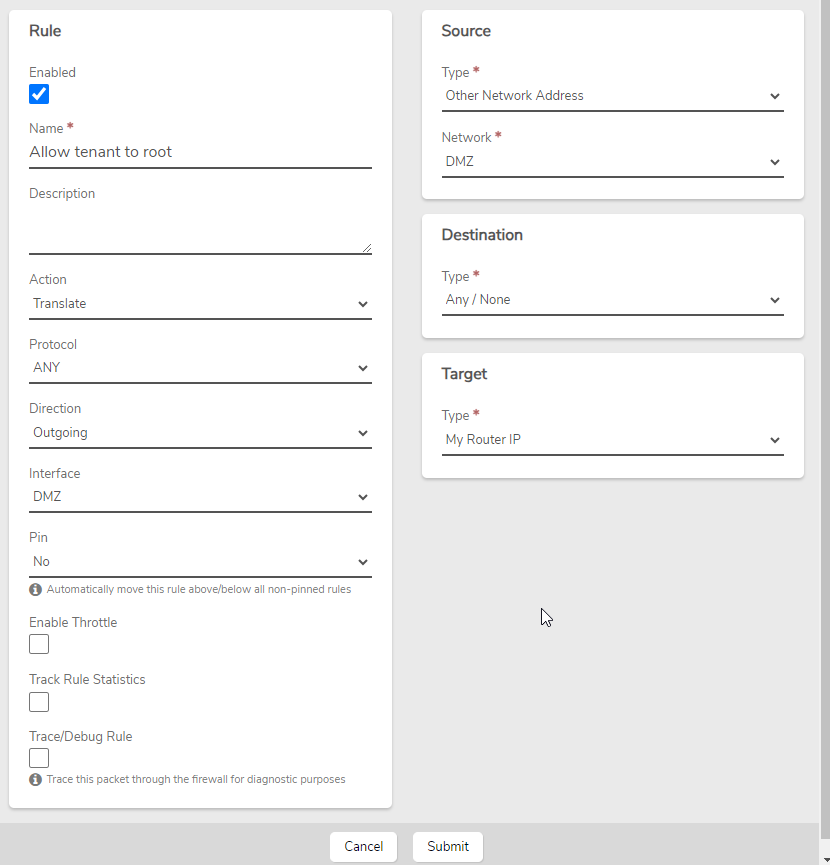
  1. Access External Networks - In the Root system, navigate to Networks and then External Networks. - Double-click on the External network.

  2. Add the Rule - In the left menu, click on Rules. - Before adding a new rule, ensure it doesn’t already exist. - Click New in the left menu. - Enter the following details:

    • Name: Enter a descriptive name such as "Allow Tenant to Root".
    • Action: Translate.
    • Protocol: ANY.
    • Direction: Outgoing.
    • Interface: DMZ.
    • Source: Other Network Address (DMZ).
    • Destination: Any/None.
    • Target: My Router IP.

Rule Configuration

  1. Submit and Apply - Click Submit. - In the left menu or at the top, click Apply Rules to activate the new rule.

After the rule is applied, the root system should now be able to connect to the tenant site.

Testing the Rule

To verify that the rule works, follow these steps:

  1. From the Home screen, click System in the left menu.
  2. Click on Nodes in the left menu.
  3. Double-click on Node1 or select Node1 and click View.
  4. In the left menu, click on Diagnostics.
  5. Change the Query to TCP Connection Test.
  6. Set Host to the UI IP/Host of the tenant system.
  7. Set Port to 443.
  8. Click Send.

The Response should say Connection successful. If the connection fails, review the rule to ensure accuracy, particularly ensuring that the Interface is set to DMZ rather than Auto.

Troubleshooting

Common Issues

  • Issue: Connection test fails.
  • Solution: Double-check that the rule is configured correctly, especially the interface settings. Also, ensure there are no blocking rules that could prevent the connection.

Additional Resources

Feedback

Need Help?

If you encounter any issues while setting up the root-to-tenant site connection, or have any questions, feel free to contact our support team.


Document Information

  • Last Updated: 2023-09-12
  • VergeOS Version: 4.12.6

Accessing the Verge.io UI from a VM

Overview

Key Points

  • Access the VergeOS UI from a VM within your environment
  • Utilize hair-pinning network technique
  • Create a specific network rule on the internal network

This article guides you through the process of setting up access to the VergeOS User Interface (UI) from a virtual machine (VM) running inside the VergeOS system. This is accomplished using a networking technique known as hair-pinning, where a packet travels to an interface, goes out towards the Internet, but instead of continuing, it makes a "hairpin turn" and comes back in on the same interface.

Prerequisites

  • A running VergeOS environment
  • A virtual machine (VM) within your VergeOS environment
  • Access to the VergeOS UI
  • Basic understanding of network rules in VergeOS

Steps

  1. Navigate to the Internal Network - Log into your VergeOS environment - Go to the internal network that your target VM is connected to

  2. Create a New Rule - Locate the option to create a new rule - Configure the rule with the following settings:

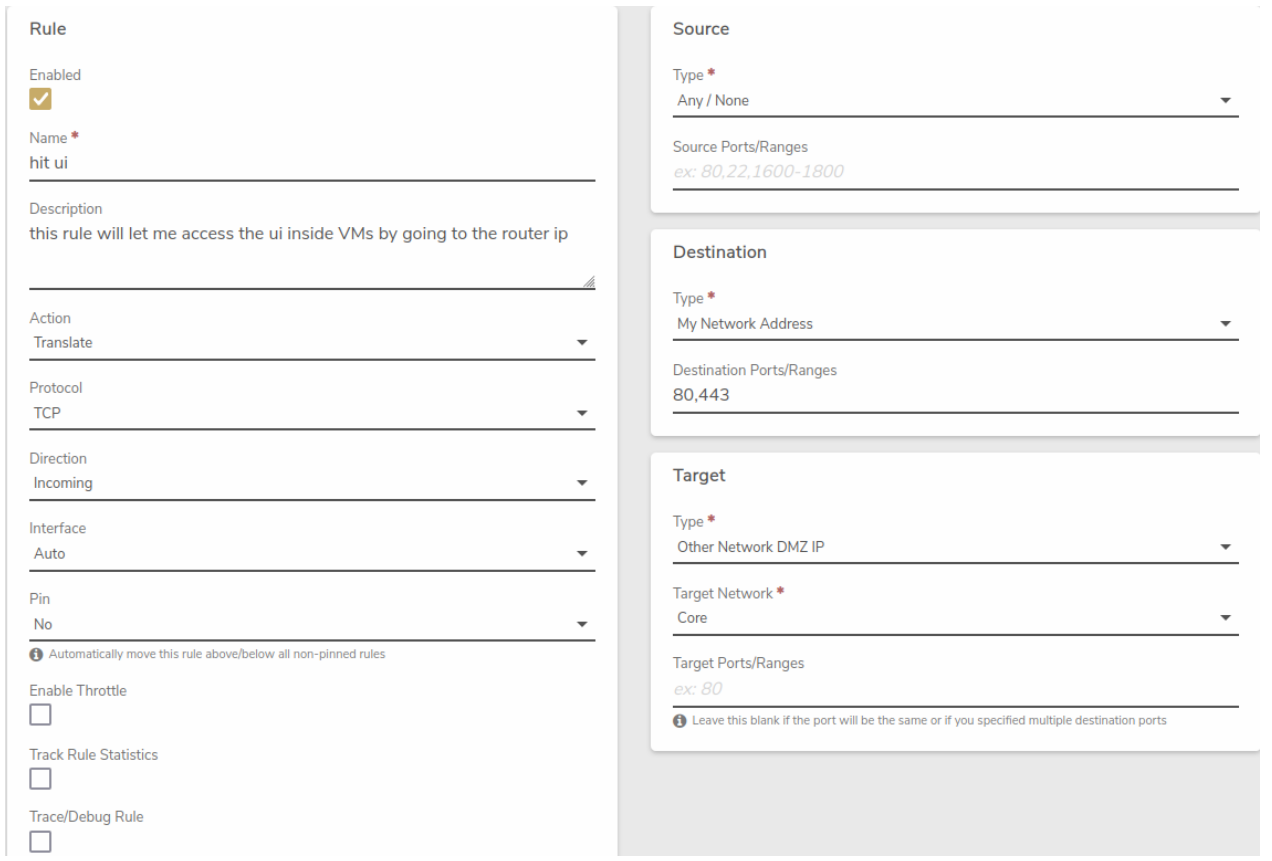
    Rule: - Name: Use a reference name, such as "Allow UI" - Action: Translate - Protocol: TCP - Direction: Incoming - Interface: Auto - Pin: No

    Source: - Type: Any / None - Source Ports/Ranges: Leave blank

    Destination: - Type: My Network Address - Destination Ports/Ranges: 80, 443

    Target: - Type: Other Network DMZ IP - Target Network: Core - Target Ports/Ranges: Leave blank

  3. Submit the Rule - Click "Submit" to save the rule

  4. Apply the New Rule - Click "Apply Rules" to activate the newly created rule

  5. Access the UI from the VM - Open a web browser within your VM - Navigate to the IP address of the internal network (e.g., if the internal network IP is 192.168.0.1, use this address)

Pro Tip

Always ensure that your VM's network settings are correctly configured to use the internal network where you've set up this rule.

Visual Guide

Here's a visual representation of the rule configuration:

hairpin.png

Troubleshooting

Common Issues

  • Problem: Unable to access the UI after creating the rule
  • Solution:
    1. Verify that the rule is applied correctly
    2. Check if the VM's network interface is on the correct internal network
    3. Ensure no firewall rules are blocking the connection

Additional Resources

Feedback

Need Help?

If you encounter any issues while setting up UI access or have questions about this process, please don't hesitate to contact our support team.


Document Information

  • Last Updated: 2024-08-29
  • VergeOS Version: 4.12.6

How to Configure Routing Between Networks

The following is a simple method to establish a route between two networks in the VergeOS platform.

Create a Network Rule on the First Network to Route Traffic to the Second Network

  1. Navigate to the first network that you would like to route traffic from.
  2. From the network dashboard, click on Rules in the left navigation menu.
  3. In the Rules menu, click on New to create a new network rule.
  4. Configure the rule with the following settings: - Rule:
    • Name: A name indicating this rule is a route to the second network.
    • Action: Route
    • Protocol: Any
    • Direction: Outgoing
    • Source:
    • Type: My Network Address
    • Destination:
    • Type: Other Network Address
    • Network: The name of the second network
    • Target:
    • Type: Other Network DMZ IP
    • Target Network: The name of the second network
  5. After completing this rule, click Submit to save the rule.

Create a Network Rule on the First Network to Allow Traffic from the Second Network

  1. From the same network dashboard, click on Rules in the left navigation menu.
  2. In the Rules menu, click on New to create a new network rule.
  3. Configure the rule with the following settings: - Rule:
    • Name: A name indicating this rule allows traffic from the second network.
    • Action: Accept
    • Protocol: Any
    • Direction: Incoming
    • Source:
    • Type: Other Network Address
    • Network: The name of the second network
    • Destination:
    • Type: My Network Address
  4. After completing this rule, click Submit to save the rule.
  5. Click Apply Rules to enable the rule.

Info

After completing the two rules on the first network, you will need to create identical rules on the second network.


Create a Network Rule on the Second Network to Route Traffic to the First Network

  1. Navigate to the second network that you would like to route traffic from.
  2. From the network dashboard, click on Rules in the left navigation menu.
  3. In the Rules menu, click on New to create a new network rule.
  4. Configure the rule with the following settings: - Rule:
    • Name: A name indicating this rule is a route to the first network.
    • Action: Route
    • Protocol: Any
    • Direction: Outgoing
    • Source:
    • Type: My Network Address
    • Destination:
    • Type: Other Network Address
    • Network: The name of the first network
    • Target:
    • Type: Other Network DMZ IP
    • Target Network: The name of the first network
  5. After completing this rule, click Submit to save the rule.

Create a Network Rule on the Second Network to Allow Traffic from the First Network

  1. From the same network dashboard, click on Rules in the left navigation menu.
  2. In the Rules menu, click on New to create a new network rule.
  3. Configure the rule with the following settings: - Rule:
    • Name: A name indicating this rule allows traffic from the first network.
    • Action: Accept
    • Protocol: Any
    • Direction: Incoming
    • Source:
    • Type: Other Network Address
    • Network: The name of the first network
    • Destination:
    • Type: My Network Address
  4. After completing this rule, click Submit to save the rule.
  5. Click Apply Rules to enable the rule.

Document Information

  • Last Updated: 2024-08-29
  • vergeOS Version: 4.12.6

Accessing the User Interface from an Internal Network

Overview

Key Points

  • Access the vergeOS UI from a VM within your environment
  • Create a route rule on the internal network
  • Simple process involving dashboard navigation and rule creation

This article guides you through the process of setting up access to the vergeOS User Interface (UI) from a virtual machine (VM) within your vergeOS environment. This is accomplished by creating a specific route rule on the network to which your VM is connected, typically an internal network.

Prerequisites

  • A running vergeOS environment
  • A virtual machine (VM) within your vergeOS environment
  • Access to the vergeOS dashboard
  • Basic understanding of network rules in vergeOS

Steps

  1. Navigate to the Network Dashboard - Log into your vergeOS environment - Go to the dashboard of the network that your target VM is connected to

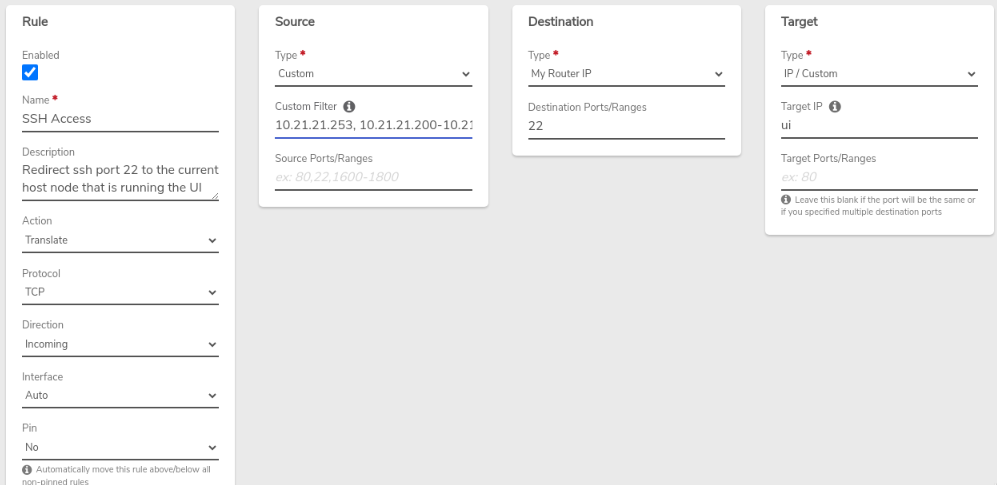
  2. Create a New Rule - Locate the option to create a new rule - Use the settings shown in the image below:

ui-access-rule.png

  1. Submit the Rule - After configuring the rule, submit it - You will be redirected to the list view of rules on the network

  2. Apply the New Rule - Click "Apply Rules" to activate the newly created rule

  3. Access the UI from the VM - Open a web browser within your VM - Navigate to the IP address of the Verge UI (e.g., https://192.168.4.1)

Pro Tip

Always ensure that your VM's network settings are correctly configured to use the internal network where you've set up this rule.

Troubleshooting

Common Issues

  • Problem: Unable to access the UI after creating the rule
  • Solution:
    1. Verify that the rule is applied correctly
    2. Check if the VM's network interface is on the correct network
    3. Ensure no firewall rules are blocking the connection

Additional Resources

Feedback

Need Help?

If you encounter any issues while setting up UI access or have questions about this process, please don't hesitate to contact our support team.


Document Information

  • Last Updated: 2024-08-29
  • vergeOS Version: 4.12.6