Skip to content

Network#

Network Diagnostics Guide

Overview

This guide provides comprehensive information about the network diagnostic options available in the user interface. These diagnostic tools enable system administrators to monitor, troubleshoot, and maintain Verge deployments effectively.

Critical Warning

The diagnostic commands detailed in this guide are powerful administrative tools. Improper usage can result in:

  • System outages
  • Service interruptions
  • Potential data loss

Exercise extreme caution and ensure proper understanding before execution.

Prerequisites

To use these diagnostic tools, you must have:

  • UI access to your VergeIO cluster
  • Note: Tenants will have their own networking, and therefore their own Network Diagnostics page.

Accessing Network Diagnostics / Issuing Diagnostic Commands

  1. Navigate to Network Diagnostics using either method:
  • From the home screen: Select the Networks count box → Networks (left menu) → Select a network (right side of the screen) → Diagnostics
  • Alternative path: Home screen → Networks (left menu) → Select a network (right side of the screen) → Diagnostics 2. Command execution:

  • Select desired command from the dropdown menu

  • Configure available options if applicable
  • Click SEND→ to execute

Command Visibility

Enable the "Show Command" option to view the exact command being executed. This can be valuable for:

  • SSH execution
  • BASH script integration
  • Advanced command automation

ARP Scan

Purpose: Scans the local network using ARP (Address Resolution Protocol) packets to discover active devices.

Details:

  • Sends ARP requests to all possible addresses in the specified network
  • Displays MAC and IP addresses of responding devices
  • Used for network discovery and inventory

CLI Syntax:

lxc-attach -n vnet3 -- arp-scan -l -I [interface]


ARP Table

Purpose: Displays the current ARP cache with IP addresses instead of hostnames.

Details:

  • Shows the ARP table maintained by the kernel
  • The -n flag prevents DNS lookups (displays numeric IP addresses)
  • Lists MAC addresses associated with IP addresses the system has communicated with

CLI Syntax:

lxc-attach -n vnet3 -- arp -n


DHCP Release/Renew

Purpose: Releases the DHCP address for the selected interface, then attempts to renew it.

Details:

  • This command sequence effectively performs a "release and renew" operation for DHCP-assigned IP addresses:
  • Release the current IP address (USR2 signal)
  • Waits for 2 seconds (sleep 2)
  • Request a new IP address (USR1 signal)

CLI Syntax:

lxc-attach -n vnet3 -- busybox sh -c killall -USR2 udhcpc ; sleep 2 ; killall -USR1 udhcpc


DNS Lookup

Purpose: Performs DNS lookups for specified query types.

Details:

  • Used for troubleshooting DNS issues and domain information gathering
  • Common query types:
  • A: IPv4 address records
  • AAAA: IPv6 address records
  • MX: Mail exchange records
  • NS: Name server records
  • TXT: Text records
  • CNAME: Canonical name records

CLI Syntax:

lxc-attach -n vnet3 -- host -t Query_Type DNS_Name


FRRouting / BGP/OSPF

Purpose: Allows the configuration of FRRouting.

Details: For more information on other values and variables, refer to FRR documentation & Configuring BGP Hold Down Timers.

CLI Syntax:

lxc-attach -n vnet3 -- vtysh -c command_goes_here


IP Commands

Purpose: Allows for the configuration of IP and it's subsequent related items.

Address

Purpose: Displays and configures network interface addresses.

Details:

  • Shows IP addresses, subnet masks, and interface states
  • Displays both IPv4 and IPv6 addresses

CLI Syntax:

lxc-attach -n vnet3 -- /sbin/ip address

Connection Tracking

Purpose: Displays the contents of Netfilter's Connection Tracking file which contains information about network connections.

Details: This file displays the current state of all tracked network connections on the system. Each line in the file represents a single tracked connection. The contents typically include entries with fields such as:

  • Protocol (tcp, udp, icmp)
  • Connection states (ESTABLISHED, TIME_WAIT, etc.)
  • Source and destination IP addresses and ports
  • Connection timeouts
  • Packet and byte counts
  • NAT information if applicable

CLI Syntax:

lxc-attach -n vnet3 -- dd bs=262144 count=1 if=/proc/net/nf_conntrack

Purpose: Displays network interfaces at layer 2 (data link layer).

Details: - Shows interface states, MTU values, and MAC addresses

CLI Syntax:

lxc-attach -n vnet3 -- /sbin/ip link

Multicast Address

Purpose: Displays multicast addresses assigned to interfaces.

Details: - Shows IPv4 and IPv6 multicast addresses - Displays which interfaces are subscribed to which multicast groups - Useful for debugging multicast routing and applications

CLI Syntax:

lxc-attach -n vnet3 -- /sbin/ip maddress

Multicast Routing Cache

Purpose: Displays multicast routing table.

Details: - Shows active multicast routes - Includes source and group addresses - Displays incoming and outgoing interfaces - Useful for troubleshooting multicast routing issues

CLI Syntax:

lxc-attach -n vnet3 -- /sbin/ip mroute

Neighbor

Purpose: Displays neighbors (ARP table) of the current device.

Details: - Similar to arp -n. - Shows IPv4 and IPv6 neighbors - Includes MAC addresses and states of neighbors

CLI Syntax:

lxc-attach -n vnet3 -- /sbin/ip neighbor

Routing Table

Purpose: Displays the IP routing table.

Details: - Shows all routes currently configured on the system - Displays default gateway, network routes, and host routes

CLI Syntax:

ip route show table all

Rule

Purpose: Displays and manipulates the routing policy database.

Details: - Shows policy-based routing rules - Allows for complex routing setups with multiple routing tables - Used for advanced networking configurations - Rules are evaluated in priority order (lower numbers first)

CLI Syntax:

lxc-attach -n vnet3 -- /sbin/ip rule

Transform (xfrm) - Policy

Purpose: Displays IPSec policies.

Details: - Shows security policies for IPSec communications - Displays source, destination, protocols, and actions

CLI Syntax:

lxc-attach -n vnet3 -- /sbin/ip xfrm policy

Transform (xfrm) - State

Purpose: Displays IPSec security associations.

Details: - Shows the current security associations (SAs) for IPSec - Displays encryption algorithms, keys, and related information - Used in conjunction with ip xfrm policy

CLI Syntax:

lxc-attach -n vnet3 -- /sbin/ip xfrm state


IPsec

Purpose: Allows for the configuration of IPsec and it's subsequent related items.

List Cryptographic Algorithms

Purpose: Lists all algorithms supported by the IPSec stack.

Details: - Displays encryption, authentication, and compression algorithms - Shows available key lengths and other parameters

CLI Syntax:

lxc-attach -n vnet3 -- ipsec listalgs

List IKE Counters

Purpose: Displays statistics and counters for IPSec connections.

Details: - Shows packet counts, bytes transferred, and errors - Useful for monitoring and troubleshooting IPSec tunnels

CLI Syntax:

lxc-attach -n vnet3 -- ipsec listcounters

IPsec Show Config

Purpose: Displays the contents of StrongSwan's VPN Configuration file which contains information about network VPN connections.

** Details**: This file contains settings for your VPN tunnels including:

  • Connection definitions
  • Authentication methods
  • Encryption algorithms
  • Network settings
  • Tunnel endpoints
  • Identity information
  • Secret key references

CLI Syntax:

lxc-attach -n vnet3 -- dd bs=262144 count=1 if=/tmp/vpn/ipsec.conf status=none

Status

Purpose: Displays the status of IPSec connections.

Details: - Shows active IPSec tunnels and their current state - Displays connection names, remote endpoints, and status - Useful for quick verification of IPSec connectivity

CLI Syntax:

lxc-attach -n vnet3 -- ipsec status

Status All

Purpose: Displays detailed status of all IPSec connections.

Details: - Shows comprehensive information about IPSec tunnels - Includes encryption algorithms, key lifetimes, traffic statistics - Displays connection policies and security associations - Valuable for in-depth troubleshooting of IPSec issues

CLI Syntax:

lxc-attach -n vnet3 -- ipsec statusall


NMAP

Purpose: Network exploration and security auditing tool.

Details: - Scans networks and hosts for open ports and services - Can determine operating systems and service versions - Supports various scanning techniques (SYN, TCP, UDP, etc.) - Offers script-based vulnerability scanning - Essential tool for network administrators and security professionals

CLI Syntax:

lxc-attach -n vnet3 -- nmap 192.168.0.1 -p22-100


Ping

Purpose: Tests connectivity to a target host.

Details: - Sends ICMP Echo Request packets and waits for ICMP Echo Reply - Measures round-trip time (latency) to the target - Shows packet loss percentage - Basic but essential network troubleshooting tool - Useful for testing basic connectivity and network performance

CLI Syntax:

lxc-attach -n vnet3 -- busybox ping -c 1 -W 5 8.8.8.8


Show Firewall Rules

Purpose: Displays the current nftables firewall ruleset.

Details: - Shows all tables, chains, and rules configured in nftables - Replacement for the older iptables command - Provides a comprehensive view of the firewall configuration - Useful for troubleshooting connectivity issues and security auditing

CLI Syntax:

lxc-attach -n vnet3 -- nft list ruleset


TCP Connection Test

Purpose: Uses netcat to connect to checkip.dyndns.org to determine your public IP address.

Details: - Establishes a TCP connection to the specified host and port - Used to determine external IP address

CLI Syntax:

lxc-attach -n vnet3 -- busybox nc -w5 checkip.dyndns.org 80


TCP Dump

Purpose: Captures and displays network packets on a specific interface.

Details: - There are multiple Verbose Output options - Checking Show Link-Level Header can aid in VLAN troubleshooting - Expressions can be used to filter the output. - Type qualifiers (host, net, port, portrange) - Direction qualifiers (src, dst) - Protocol qualifiers (ether, ip, ip6, tcp, udp, icmp, arp) - Logical operators (and, or, not) - Advanced filters (greater than, less than, TCP flags, byte offsets)

CLI Syntax:

lxc-attach -n vnet3 -- busybox timeout 15 tcpdump -lni eth0 -c 100


Top CPU Usage

Purpose: Displays system process information in batch mode for a single iteration.

Details: - Shows CPU, memory, and process details - Useful for system monitoring and troubleshooting performance issues

CLI Syntax:

lxc-attach -n vnet3 -- /usr/bin/top -b -n 1


Top Network Usage

Purpose: Displays bandwidth usage on a network interface by host.

Details: - Shows real-time bandwidth usage by connection - Useful for identifying which hosts are using the most bandwidth

CLI Syntax:

lxc-attach -n vnet3 -- busybox timeout 10 /usr/sbin/iftop -tNi eth0 -n


Trace Route

Purpose: Traces the route packets take to a destination.

Details: - Displays each hop (router) between your computer and the destination - Shows round-trip time for each hop - Useful for diagnosing routing issues and network latency problems

CLI Syntax:

traceroute -n -w 3 google.com


Trace/Debug Firewall Rules

Purpose: Monitors and traces packets as they traverse nftables rules.

Details: - Shows which rules packets match and the resulting actions - Extremely useful for debugging complex firewall configurations - Requires root privileges

CLI Syntax:

lxc-attach -n vnet3 -- busybox timeout 3 nft -nnn monitor trace


What's My IP

Purpose: Queries OpenDNS to determine your public IP address.

Details: - Simple, reliable method to determine your public IP address - Works even when HTTP-based services might be blocked

CLI Syntax:

lxc-attach -n vnet3 -- dig +short myip.opendns.com @208.67.222.222


Additional Resources

Feedback

Need Help?

If you need further assistance or have any questions about this article, please don't hesitate to reach out to our support team.

Document Information

  • Last Updated: 2024-03-21
  • VergeOS Version: 4.13.4

Provide Layer 2 Access to a Tenant

Key Points

  • These instructions pertain to environments with specific requirements for tenant layer 2 connectivity (e.g. utilizing existing non-virtualized network infrastructure or tenant customers with direct MPLS lines, etc.)
  • Virtual Wires (virtual network uplinks) are used.

High-Level Steps

  1. Prepare the physical network: verify VLANs are configured on the appropriate physical switch ports so that they are accessible within the VergeOS environment.

Warning

VLANs 1 & 100-102 cannot be used in a virtual wire capacity. These VLANs are reserved for internal traffic. These IDs can, however, be remapped to other VLAN IDs for tenant consumption.

  1. Create the Virtual Wire Determine whether the tenant will need access to a single VLAN or multiple VLANs. This will determine the virtual wire configuration:

Virtual Wire Host Placement

When using a virtual wire, both networks participating in that virtual wire must be on the same host. Failure to meet this requirement can lead to network connectivity issues.

  1. Add VLANs Inside the Tenant

Creating a 1:1 Virtual Wire

  1. Ensure the VLAN(s) have been configured in the VergeOS UI. If not, follow the steps to create VLAN(s) here.
  2. From the Main Dashboard, select Networks in the left menu to open the Networks Dashboard.
  3. Select Virtual Wires in the left menu to view all virtual wires in the environment.
  4. Select New to create the first half of the virtual wire:

    • Name: a descriptive name, e.g., VLAN from host, etc.
    • Network: the external network with the corresponding VLAN to pass to the tenant
    • Destination Wire: field should display --Empty List-- or select --None--
    • PVID: 1.
      Example Configuration: virtual-wire-create-settings.png
  5. Submit your changes and return to the virtual wires list view.

  6. Select New to create the second half of the virtual wire:

    • Name: a name to identify the wire such as vlan id, tenant, purpose, etc
    • Network: the tenant network, typically named tenant_'$TENANTNAME'.
    • Destination Wire: the other half of the virtual wire created above.
    • PVID: VLAN ID of the network being attached.
      Example Configuration: virtual-wire-create-settings-tenant.png
  7. Submit your changes.

  8. Navigate to the Networks Dashboard, select Networks, and Apply Rules for both networks connected by the virtual wires.

Creating a Trunk Mode Virtual Wire

Bridge Mode Required

To use trunk mode virtual wires, the corresponding physical network (tied to node NICs) must be set to Bridge mode.

Set the Physical Network to Bridge Mode

  1. Navigate to Networks in the left menu to access the Networks Dashboard.
  2. Select Networks again to view all networks in the environment.
  3. Double-click the Physical Network (NIC) that the VLANs are trunked to on the physical switch.

Tip

A physical Network typically has "Switch" appended to the name and represents a physical NIC on a node.

  1. Select Edit to enter the network configuration page.
  2. In the configuration page, enable Physical Bridged to activate Bridge Mode. It is best to set the On Power Loss setting to Power On so that the network starts up automatically after a system power loss.
  3. Submit your changes.
  4. Reboot the necessary nodes for Bridge Mode to become active.

Follow proper Maintenance Mode procedures when rebooting a node to avoid workload disruptions.

Configuring a Trunk Mode Virtual Wire

  1. Ensure the physical network is set to Bridged Mode and is powered on.
  2. From the Main Dashboard, navigate to Networks > Virtual Wires.
  3. Select New to create the first half of the virtual wire.

    • Name: identify the wire, e.g., "trunk from host"
    • Network: physical network with the corresponding VLAN to pass to the tenant.
    • Destination Wire: should display --Empty List-- or select --None--
    • PVID: 0
    • Allowed VLAN List: comma-delimited and with ranges as necessary
      Example Configuration: vw-trunk-host.png
  4. Submit your configuration.

  5. Select New to create the second half of the virtual wire.

    • Network dropdown, select the tenant network that the VLAN will be passed to, typically named tenant_'$TENANTNAME'.
    • PVID: 0
    • Allowed VLAN List: comma-delimited and with ranges as necessary
      Example Configuration: vw-trunk-tenant.png
  6. Submit your changes.

  7. Navigate to the Networks Dashboard, select Networks, and Apply Rules for both networks connected by the virtual wires.

Add VLANs Inside the Tenant

  1. Navigate to the tenant UI and log in.
  2. From the Main Dashboard, navigate to Networks, then select New External.
  3. Configure settings:
    • Name: a label to identify the network (name, vlan ids, purpose, etc.)
    • Layer 2 Type: VLAN
    • Layer 2 ID: VLAN ID
    • Interface Network: Physical
    • IP Address Type: None
      Example Configuration: virtual-wire-network-in-tenant.png

Leave other fields at default settings unless specific configuration needed. For information about additional external network options, see: How to Create an External Network

  1. Submit your configuration.
  2. Attach workloads to the network for Layer 2 access to networks outside VergeOS.

Troubleshooting Steps

Traffic is not reaching the virtual machine

  • Confirm firewall rules related to the virtual wire have been applied.
  • Verify the destination tenant network and VLAN network are in the "Running" state and reside on the same physical node.
  • Ensure VLANs are trunked to the correct physical node ports.

Document Information

  • Last Updated: 2024-09-03
  • VergeOS Version: 4.12.6

Change External Network to Bonded with Tagged VLAN

Overview

Key Points

  • This procedure creates an active-backup bond across vlanned physical networks.
  • It is recommended for bare-metal installations with a limitation of 2 NICs per node.
  • System downtime is not required to make this change.

This guide outlines the process to create a bonded external network across vlanned physical networks. The outlined method provides optimal redundancy for bare-metal installations that are limited to two NICs per node, allowing for two independent core-fabric networks and a single-VLAN, bonded external network.

Prerequisites

Warning

  • This process should be performed with local server access because external network changes can affect remote UI access. This will also allow you to test the bond configuration by removing one of the network cables to verify expected bond failover.
  • Before making any significant system changes confirm you have the name/password for the "admin" user (user ID #1 (1)), in case command-line operations become needed.
  1. Hint: "Key=1" parameter is in the URL of the user's dashboard

Steps

  1. Navigate to the external network dashboard (Main Dashboard > Networks > Externals > double-click external network) and click Edit on the left menu.
  2. Change Layer 2 Type to vLAN and enter appropriate Layer 2 ID (VLAN number).
  3. Select the checkbox option for both physical networks.
  4. Click Submit to save the change.

Post Configuration

  1. Check the external network by accessing the UI from a remote connection.
  2. Test Bond failover: Navigate to the external network dashboard and select NICs to view the network adapters. Physically disconnect one network cable. The UI should now indicate the NIC is in a "Down" status; verify remote UI access is still available.

Verify core network redundancy is in place before disconnecting network cables.

Troubleshooting

Common Issues

  • Problem: Loss of remote access
  • Solution:
    1. Check correct VLAN was entered in the external network config
    2. Verify network switch ports are correctly configured for the VLAN tag.

Additional Resources

Feedback

Need Help?

If you need further assistance or have any questions about this article, please don't hesitate to reach out to our support team.


Document Information

  • Last Updated: 2024-11-26
  • vergeOS Version: 4.13.1

Configuring BGP Hold Down Timers

BGP (Border Gateway Protocol) hold timers are critical for maintaining stable BGP sessions between routers. This document will guide you through configuring the BGP hold down timers to 5 seconds for the keepalive interval and 15 seconds for the hold time.

Prerequisites

  1. Basic BGP Configuration: You should have a basic BGP configuration set up.
  2. Basic Knowledge of FRR Configuration: Familiarity with FRR configuration commands and procedures.

Configuration Steps

Step 1: Setup BGP

  1. Create a new External Network.
  2. Set its IP address type to BGP/OSPF.
  3. Set an ASN (Autonomous System Number).
  4. Define the IP address and Network Address.
  5. If this is a VLAN, configure the Layer 2 ID.
  6. Select an interface network.

Step 2: Open the BGP Network

  1. Open the network you created.
  2. Select Routers from the left menu.
  3. Open the ASN you defined during network creation.
  4. Select New from the left menu.
  5. Select Timers from the command menu.
  6. Under Parameters, enter bgp x y where x is the keepalive interval and y is the hold time. For example, bgp 5 15.
  7. Select Submit. This will return you to the Router page.
  8. Navigate back to the BGP network. A restart is required for the recent changes to take effect. Click Restart to apply changes.

Step 3: Verify the Setting

  1. Navigate back to the BGP network you configured.
  2. Select Network Diagnostics from the left menu.
  3. Choose FRRRouting BGP/OSPF from the Query dropdown.
  4. Run the default command show running-config.
  5. The settings modified in Step 2 should now appear in the running configuration.

For more information on other values and variables, refer to the FRR documentation.

How to Create an External Network

This guide provides steps for creating an external network in VergeOS. The example assumes that the physical network in VergeOS is named External Switch, the VLAN for the new network is 50, and a static IP address is being used.

Steps

  1. Access Network Configuration:
  • From the home screen of the UI, click on Networks and select New External.
  1. Configure Network Settings:
  • Network Name: Enter a name for your network. In this example, use WAN1.
  • Layer 2 Type: Set to vLAN.
  • Layer 2 ID: Enter the VLAN ID, in this example, 50.
  • MTU: Leave as 1500 (Advanced users may adjust this as needed).
  • Interface Network: Select the physical network, in this example, External Switch.
  1. Configure Network Router:
  • IP Address Type: Select Static. (If using DHCP, select it here and skip the remaining router steps).
  • IP Address: Enter the IP address for this network. Example: 192.168.212.2.
  • Network Address: Enter the network address in CIDR format. Example: 192.168.212.0/24.
  • Gateway Monitoring: Enabling this feature is recommended for network reliability.
  1. Save and Activate the Network:
  • Click Save and wait for the network to power on. Once it displays as Running, proceed to set up routing rules.
  1. Add Default Routing Rule:
  • Click on Rules and select New.
  • Rule Name: Enter a name for this rule, such as default route.
  • Action: Select Route.
  • Direction: Choose Outgoing.
  • Source and Destination Filters: Leave as any and default since this is the default route.
  • Target:
    • Type: Select IP/Custom.
    • Target IP: Enter the router IP of your gateway. Example: 192.168.212.1.
  • Click Save, then Apply Rules.

Feedback

Need Help?

If you have any questions or encounter issues while creating an external network, please reach out to our support team for assistance.


Document Information

  • Last Updated: 2024-10-30
  • VergeOS Version: 4.12.6

Network Blocks

Network Blocks Overview

Network blocks in VergeOS are a powerful way to assign multiple IP addresses to tenants or networks for workloads. This method is preferred over virtual wires since VergeOS focuses on Layer 3 connectivity, avoiding the common issues associated with Layer 2 connections (like virtual wires). Network blocks also allow the direct assignment of public IP addresses to VMs inside an internal network or a tenant.

Creating a Network Block

  1. In the VergeOS UI, navigate to the External Network where the network block will originate.
  2. In the left menu, select Network Blocks, then click New.
  3. Enter the network block information in CIDR notation (e.g., a.b.c.d/n).
  4. To assign the block to a tenant at creation, set the Owner Type to Tenant, then select the tenant from the Owner drop-down.
  5. Submit your work to create the block.
  6. To apply the automatically created rules, select the External breadcrumb in the header to return to the network dashboard. Then, select Apply Rules from the left menu or click the notification pop-up.

Creating a Network from a Network Block

  1. Log in to the tenant's URL with the necessary credentials.
  2. Navigate to Networks, then go to the External Network Dashboard.
  3. In the left menu, select Network Blocks.
  4. Select the network block assigned to the tenant.
  5. Click New Network in the left menu.
  6. Give the new network a name. The rest of the details will be pre-filled based on the CIDR information.
  7. Modify any details in the form if necessary, then submit to create the network.
  8. After creation, the system will redirect you to the new network's dashboard. The necessary routes and accept rules will be set up automatically, but note that inbound traffic will be dropped by default. Add appropriate firewall rules to allow inbound access.
  9. Power on the network using the option in the left menu.
  10. Assign any desired virtual machines to the network and test connectivity.

Document Information

  • Last Updated: 2024-08-29
  • vergeOS Version: 4.12.6

Allow Root to Tenant Site Connection

Overview

Important

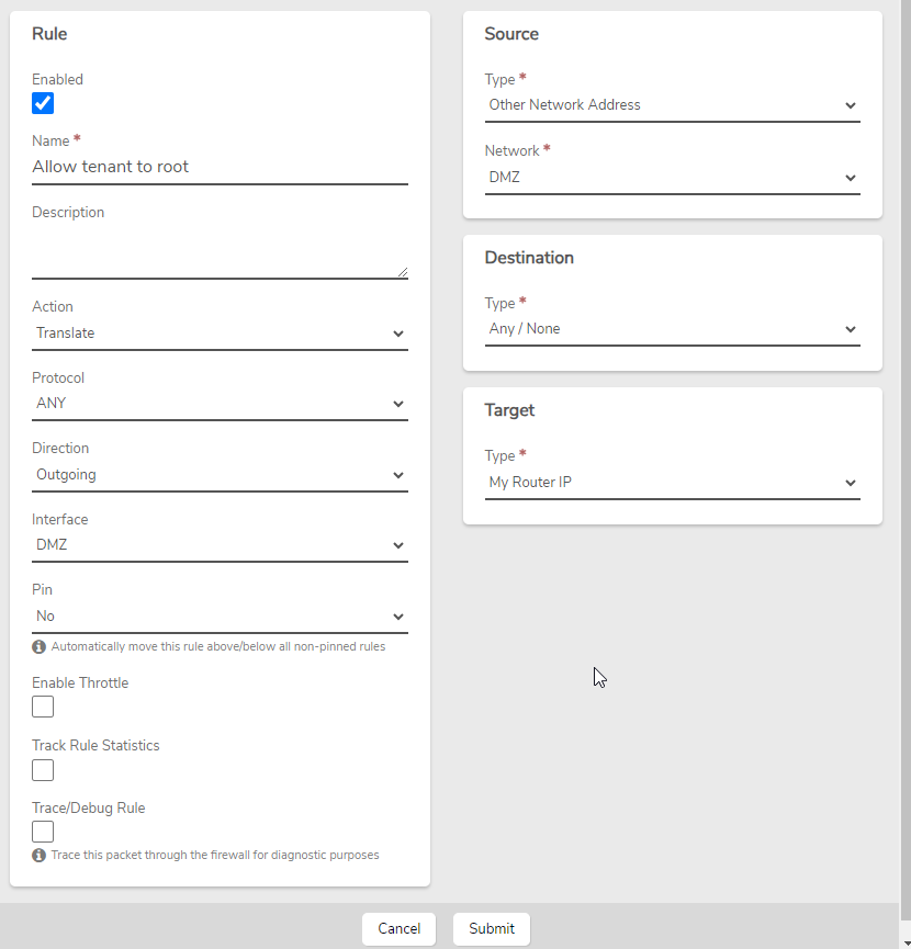
Adding this rule will allow tenants to connect on the DMZ network. By default, this is disabled for security reasons.

This guide provides instructions on how to connect a root system to a tenant site in VergeOS. The Sites feature is typically used to connect two VergeOS sites together, but to extend this functionality to a tenant site, you’ll need to add a specific rule on the root system's External network.

Prerequisites

  • Access to the Root system with administrative privileges.
  • A basic understanding of network rules and DMZ interfaces in VergeOS.

Steps

  1. Access External Networks - In the Root system, navigate to Networks and then External Networks. - Double-click on the External network.

  2. Add the Rule - In the left menu, click on Rules. - Before adding a new rule, ensure it doesn’t already exist. - Click New in the left menu. - Enter the following details:

    • Name: Enter a descriptive name such as "Allow Tenant to Root".
    • Action: Translate.
    • Protocol: ANY.
    • Direction: Outgoing.
    • Interface: DMZ.
    • Source: Other Network Address (DMZ).
    • Destination: Any/None.
    • Target: My Router IP.

Rule Configuration

  1. Submit and Apply - Click Submit. - In the left menu or at the top, click Apply Rules to activate the new rule.

After the rule is applied, the root system should now be able to connect to the tenant site.

Testing the Rule

To verify that the rule works, follow these steps:

  1. From the Home screen, click System in the left menu.
  2. Click on Nodes in the left menu.
  3. Double-click on Node1 or select Node1 and click View.
  4. In the left menu, click on Diagnostics.
  5. Change the Query to TCP Connection Test.
  6. Set Host to the UI IP/Host of the tenant system.
  7. Set Port to 443.
  8. Click Send.

The Response should say Connection successful. If the connection fails, review the rule to ensure accuracy, particularly ensuring that the Interface is set to DMZ rather than Auto.

Troubleshooting

Common Issues

  • Issue: Connection test fails.
  • Solution: Double-check that the rule is configured correctly, especially the interface settings. Also, ensure there are no blocking rules that could prevent the connection.

Additional Resources

Feedback

Need Help?

If you encounter any issues while setting up the root-to-tenant site connection, or have any questions, feel free to contact our support team.


Document Information

  • Last Updated: 2023-09-12
  • VergeOS Version: 4.12.6

Troubleshooting VM Network Connectivity Issues

Before you begin, verify if other virtual machines in the environment can access the internet. If no other machines can, there may be a network issue upstream of the VergeOS platform that is preventing access to the outside world. If other VMs are still able to access the internet, the most likely cause is that a configuration step was missed.

The following are the most common configuration mistakes that cause network issues:

  • Missing NIC Configuration: The newly created VM may not have a NIC configured. To verify this, review the NICs section of the VM dashboard. Ensure at least one NIC is present. If not, add one.
  • Incorrect Network Assignment: The VM's NIC may be connected to the wrong network. In the NICs section, ensure at least one NIC is present with the status set to Up, and verify that the correct network is listed. If not, edit the NIC and assign the correct network (one used by a VM with internet access).
  • Improper IP Configuration: The VM might not have a properly configured IP address. Typically, this is resolved at the guest level. Refer to the guest operating system’s documentation to ensure the NIC is detected, installed (with drivers), and configured correctly.
  • Virtio Drivers Not Installed: If the Virtio drivers are not installed, the NIC may not function properly. For instructions on installing Virtio drivers, refer to the Product Guide.

Document Information

  • Last Updated: 2024-09-03
  • VergeOS Version: 4.12.6

Accessing the Verge.io UI from a VM

Overview

Key Points

  • Access the VergeOS UI from a VM within your environment
  • Utilize hair-pinning network technique
  • Create a specific network rule on the internal network

This article guides you through the process of setting up access to the VergeOS User Interface (UI) from a virtual machine (VM) running inside the VergeOS system. This is accomplished using a networking technique known as hair-pinning, where a packet travels to an interface, goes out towards the Internet, but instead of continuing, it makes a "hairpin turn" and comes back in on the same interface.

Prerequisites

  • A running VergeOS environment
  • A virtual machine (VM) within your VergeOS environment
  • Access to the VergeOS UI
  • Basic understanding of network rules in VergeOS

Steps

  1. Navigate to the Internal Network - Log into your VergeOS environment - Go to the internal network that your target VM is connected to

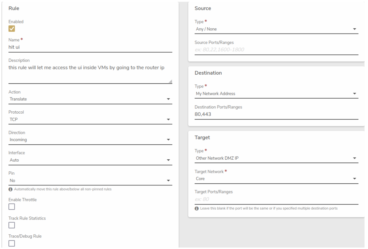
  2. Create a New Rule - Locate the option to create a new rule - Configure the rule with the following settings:

    Rule: - Name: Use a reference name, such as "Allow UI" - Action: Translate - Protocol: TCP - Direction: Incoming - Interface: Auto - Pin: No

    Source: - Type: Any / None - Source Ports/Ranges: Leave blank

    Destination: - Type: My Network Address - Destination Ports/Ranges: 80, 443

    Target: - Type: Other Network DMZ IP - Target Network: Core - Target Ports/Ranges: Leave blank

  3. Submit the Rule - Click "Submit" to save the rule

  4. Apply the New Rule - Click "Apply Rules" to activate the newly created rule

  5. Access the UI from the VM - Open a web browser within your VM - Navigate to the IP address of the internal network (e.g., if the internal network IP is 192.168.0.1, use this address)

Pro Tip

Always ensure that your VM's network settings are correctly configured to use the internal network where you've set up this rule.

Visual Guide

Here's a visual representation of the rule configuration:

hairpin.png

Troubleshooting

Common Issues

  • Problem: Unable to access the UI after creating the rule
  • Solution:
    1. Verify that the rule is applied correctly
    2. Check if the VM's network interface is on the correct internal network
    3. Ensure no firewall rules are blocking the connection

Additional Resources

Feedback

Need Help?

If you encounter any issues while setting up UI access or have questions about this process, please don't hesitate to contact our support team.


Document Information

  • Last Updated: 2024-08-29
  • VergeOS Version: 4.13.3

How to Configure Routing Between Networks

The following is a simple method to establish a route between two networks in the VergeOS platform.

Create a Network Rule on the First Network to Route Traffic to the Second Network

  1. Navigate to the first network that you would like to route traffic from.
  2. From the network dashboard, click on Rules in the left navigation menu.
  3. In the Rules menu, click on New to create a new network rule.
  4. Configure the rule with the following settings: - Rule:
    • Name: A name indicating this rule is a route to the second network.
    • Action: Route
    • Protocol: Any
    • Direction: Outgoing
    • Source:
    • Type: My Network Address
    • Destination:
    • Type: Other Network Address
    • Network: The name of the second network
    • Target:
    • Type: Other Network DMZ IP
    • Target Network: The name of the second network
  5. After completing this rule, click Submit to save the rule.

Create a Network Rule on the First Network to Allow Traffic from the Second Network

  1. From the same network dashboard, click on Rules in the left navigation menu.
  2. In the Rules menu, click on New to create a new network rule.
  3. Configure the rule with the following settings: - Rule:
    • Name: A name indicating this rule allows traffic from the second network.
    • Action: Accept
    • Protocol: Any
    • Direction: Incoming
    • Source:
    • Type: Other Network Address
    • Network: The name of the second network
    • Destination:
    • Type: My Network Address
  4. After completing this rule, click Submit to save the rule.
  5. Click Apply Rules to enable the rule.

Info

After completing the two rules on the first network, you will need to create identical rules on the second network.


Create a Network Rule on the Second Network to Route Traffic to the First Network

  1. Navigate to the second network that you would like to route traffic from.
  2. From the network dashboard, click on Rules in the left navigation menu.
  3. In the Rules menu, click on New to create a new network rule.
  4. Configure the rule with the following settings: - Rule:
    • Name: A name indicating this rule is a route to the first network.
    • Action: Route
    • Protocol: Any
    • Direction: Outgoing
    • Source:
    • Type: My Network Address
    • Destination:
    • Type: Other Network Address
    • Network: The name of the first network
    • Target:
    • Type: Other Network DMZ IP
    • Target Network: The name of the first network
  5. After completing this rule, click Submit to save the rule.

Create a Network Rule on the Second Network to Allow Traffic from the First Network

  1. From the same network dashboard, click on Rules in the left navigation menu.
  2. In the Rules menu, click on New to create a new network rule.
  3. Configure the rule with the following settings: - Rule:
    • Name: A name indicating this rule allows traffic from the first network.
    • Action: Accept
    • Protocol: Any
    • Direction: Incoming
    • Source:
    • Type: Other Network Address
    • Network: The name of the first network
    • Destination:
    • Type: My Network Address
  4. After completing this rule, click Submit to save the rule.
  5. Click Apply Rules to enable the rule.

Document Information

  • Last Updated: 2024-08-29
  • vergeOS Version: 4.12.6